


T
able
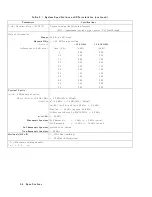
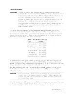
3-1.
System
Specifications
and
Characteristics
(continued)
P
arameters
Sp ecications
Sc
alar
Dynamic
R
ange
(20-30
C)
Compute
using
the
following
formula:
SDR
=
maxim
um
lev
eled
output
p o
w
er
-
TG
feedthrough
Output
A
tten
uator:
Range
55
dB
in
5
dB
steps
Rep eatabilit
y
60.2
dB
for
an
y
setting
A
c
cur
acy
<12.8
GHz
12.8-18
GHz
(referenced
to
0
dB
attn.)
A
ttn.
(dB)
(6dB)
(6dB)
5
0.40
0.50
10
0.60
0.70
15
0.85
1.00
20
0.70
0.90
25
0.95
1.15
30
0.90
1.20
35
1.25
1.60
40
1.80
2.00
45
2.00
2.20
50
2.00
2.30
55
2.20
2.50
Sp ectral
Purit
y
:
(with
02
dBm
output
p o
w
er)
Phase
Noise
at
10
kHz
oset
<
-90
dBc/Hz
+
20logN
*
Sideb
ands
n
y
240
kHz:
<
-70
dBc/Hz
+
20logN
(n250),
(n260),
and
(n2400
Hz):
<050
dBc
Display:
<060
dBc
(appro
x.
24
kHz)
Others
con
tributed
b
y
HP
70301A:
<080
dBc
n21st
LO
<065
dBc
Harmonic
Spurious
2nd
harmonic:
<07
dBc
(<015
dBc
t
ypical)
3rd
harmonic:
<011
dBc
(<015
dBc
t
ypical)
Sub-harmonic
Spurious
precluded
b
y
design
Non-harmonic
Spurious
<-60
dBc
Residuals
(RF
o
)
<0120
dBm
(trac
king)
<065
dBm
(LO
emission)
*
N
=
Harmonic
mixing
n
um
b er
y
n
=
1,
2,
3,
.
.
.
1
3-4
Specifications
Summary of Contents for 70301A
Page 6: ......
Page 10: ......
Page 16: ...Figure 1 2 Front Panel and Rear Panel Features 1 6 General Information ...
Page 20: ...Figure 1 3 Packaging Materials for HP 70001A Mainframe 1 10 General Information ...
Page 21: ...Figure 1 4 Packaging Materials for Modules General Information 1 11 ...
Page 26: ......
Page 32: ...Figure 2 3 HP 71210C with HP 70300A and HP 70301A Rear Panel Cabling 2 6 Installation ...
Page 50: ......
Page 58: ......