


Note
If
the
User
Screen
softkeys
do
not
app ear
after
p o
w
er-up,
the
display
windo
w
probably
is
not
assigned
to
a
master.
T
o
assign
it
to
the
master
with
the
low
est
column
address,
press
4
DSP
5,
then
NNNNNNNNNNNNNNNNNNNNNNNNNNNNNNNNNNNNNN
SELECT
INSTR
.
T
o
assign
the
display
to
the
master
with
the
next-highest
column
address,
press
the
up-arro
w
k
ey
,
4
8
5.
7.
If
y
ou
connect
HP-IB
cables
after
p o
w
er-on,
reset
all
instrumen
ts
on
the
bus
b
y
cycling
the
p o
w
er.
(Most
plotters
and
prin
ters
can
b e
reset
with
the
fron
t-panel
reset
k
eys
or
b
y
turning
the
main
p o
w
er
o,
then
on.)
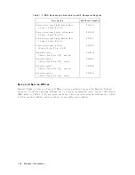
8.
Chec
k
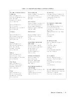
HP-MSIB
addressing
b
y
pressing
4
DSP
5
and
NNNNNNNNNNNNNNNNNNNNNNNNNNNNNNNNNNN
ADDRESS
MAP
.
Eac
h
address
consists
of
a
row
n
um
b er
and
a
column
n
um
b er.
9.
V
erify
mo
dule
op eration
using
test
describ ed
in
Chapter
4.
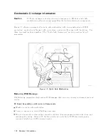
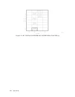
Figure
2-1.
Module
Remo
v
al/Replacement
Remo
v
al
1.
Set
the
instrumen
t
LINE
switch
to
OFF,
then
remov
e
the
rear-panel
coaxial
cables.
2.
Swing
do
wn
the
fron
t
do or,
then
use
the
8
mm
hex-ball
driv
er
to
lo
osen
the
mo
dule
latch.
3.
Slide
the
mo
dule
out
of
the
mainframe.
2-2
Installation
Summary of Contents for 70301A
Page 6: ......
Page 10: ......
Page 16: ...Figure 1 2 Front Panel and Rear Panel Features 1 6 General Information ...
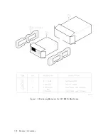
Page 20: ...Figure 1 3 Packaging Materials for HP 70001A Mainframe 1 10 General Information ...
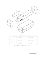
Page 21: ...Figure 1 4 Packaging Materials for Modules General Information 1 11 ...
Page 26: ......
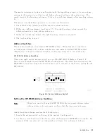
Page 32: ...Figure 2 3 HP 71210C with HP 70300A and HP 70301A Rear Panel Cabling 2 6 Installation ...
Page 50: ......
Page 58: ......