Model 3300A
Section VII
SECTION VII
REPLACEABLE PARTS
7-1.
INTRODUCTION.
7-2.
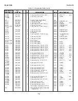
This section contains information for ordering
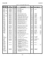
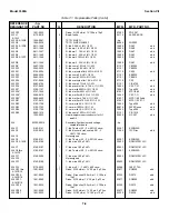
replacement parts. Table 7-1 lists parts in alphanumeric
order of their reference designators and indicates the
description, -hp- part number of each part, together with
any applicable notes, and provides the following:
a. Hewlett-Packard number.
b. Total quantities of each part used in the
instrument(TQ column).
c. Descriptions (abbreviations are listed below).
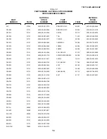
d. Table 7-2 is a part number-national stock
number cross reference index. The items on this
cross reference index are source coded PHAZZ.
Items that do not appear on this index are source
coded XD and shall be procured using the FSCM
and the MPN at the nearest wholesale level.
7-4.
ORDERING INFORMATION.
7-5.
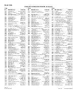
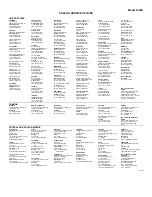
To obtain replacement parts, address order or
inquiry to your local Hewlett-Packard Field Office. (See
field office location list). Identify parts by their Hewlett-
Packard part numbers. Include instrument model and
serial numbers.
7-6.
NON-LISTED PARTS.
7-7.
To obtain a part that is not listed, include:
a. Instrument model number.
b. Instrument serial number.
c. Description of the part.
d. Function and location of the part.
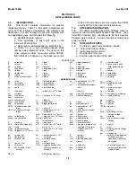
DESIGNATORS
A
= assembly
F
= fuse
MP
= mechanical part
TC
= thermocouple
B
= motor
FL
= filter
P
= plug
V
= vacuum tube, neon
BT
= battery
HR
= heater
Q
= transistor
bulb, photocell, etc.
C
= capacitor
IC
= integrated circuit
QCR
= transistor-diode
W
= cable
CR
= diode
J
= jack
R
= resistor
X
= socket
DL
= delay line
K
= relay
RT
= thermistor
XDS
= lampholder
DS
= lamp
L
= inductor
S
= switch
XF
= fuseholder
E
= misc electronic part
M
= meter
T
= transformer
Z
= network
ABBREVIATIONS
Ag
= silver
ID
= inside diameter
ns
= nanosecond (s) = 10
-9
sl
= slide
Al
= aluminum
impg
= impregnated
seconds
SPDT = single-pole double-
A
= ampere (a)
incd
= incandescent
nsr
= not separately replace-
throw
Au
= gold
ins
= insulation (ed)
able
SPA.T = single-pole single-
throw
C
= capacitor
k
Ò
=kilohm (s) = 10
+3
ohms
Ò
= ohm (s)
Ta
= tantalum
cer
= ceramic
obd
= order by description
TC
= temperature coefficient
coef
= coefficient
kHz
= kilohertz = 10
+3
hertz
OD
= outside diameter
TiO
2
= titanium dioxide
com
= common
comp = composition
L
= inductor
tog
= toggle
conn
= connection
lin
= linear taper
p
= peak
tol
= tolerance
dep
= deposited
log
= logarithmic taper
pc
= printed circuit
trim
= trimmer
DPDT = double-pole double-
pF
= picofarad (s) = 10
-12
TSTR = transistor
throw
m
= milli =10
-3
farads
DPA.T = double-pole single-
mA
= milliampere (s) = 10
+3
piv
= peak inverse voltage
V
= volt (s)
throw
amperes
p/o
= part of
vacw
= alternating current
MHz
= megahertz =10
+6
hertz
pos
= position (s)
working voltage
elect
= electrolytic
M
Ò
= megohm (s) = 10
+6
ohms
poly
= polystyrene
var
= variable
encap = encapsulated
met flm= metal film
pot
= potentiometer
vdcw
= direct current working
mfr
=manufacturer
p-p
= peak-to-peak
voltage
F
= farad (s)
mtg
= mounting
ppm
= parts per million
FET
= field effect transistor
mV
= millivolt (s) = 10
-3
volts
prec
= precision (temperature
W
= watt (s)
fxd
= fixed
Î
micro = 10
-6
coefficient, long term
w/
= with
GaAs = gallium arsenide
Î
V
= microvolt (s) = 10
-6
volts
stability, and/or tol-
wlv
= working inverse voltage
GHz
= gigahertz = 10
+9
hertz
my
= Mylar®
erance)
w/o
= without
ww
= wirewound
gd
= guard (ed)
nA
= nonoampere (s) = 10
-9
R
= resistor
*
= optimum value selected
Ge
= germanium
amperes
Rh
= rhodium
at factory, average
grd
= ground (ed)
NC
= normally closed
rms
= root-mean-square
value shown (part may
Ne
= neon
rot
= rotary
be omitted)
H
= henry (ies)
NO
= normally open
Hg
= mercury
NPO
= negative positive zero
Se
= selenium
**
= no standard type num-
Hz
= hertz (cycle (s) per
(zero temperature co-
sect
= section (s)
ber assigned (selected
second)
efficient)
Si
= silicon
or special type)
REV G
® Dupont de Nemours
7-1
Summary of Contents for 3300A
Page 31: ...Model 3300A Section VI Figure 6 1 3300A Top and Bottom Views 6 2 ...
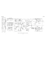
Page 32: ...Model 3300A Section VI Figure 6 2 Oscillator Circuit Schematic A11 A13 and A14 6 3 ...
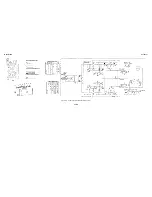
Page 33: ...Model 3300A Section VI Figure 6 4 Output Amplifiers Schematic A15 and A16 6 5 6 6 ...
Page 34: ...TM 11 6625 2495 14 P THIS PAGE CURRENTLY NOT AVAILABLE FOR DIGITIZATION PAGE Figure 6 3 6 4 ...
Page 35: ...Model 3300A Section VI Figure 6 5 Power Supply Schematic A12 and A11 6 7 6 8 ...
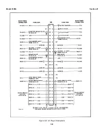
Page 36: ...Model 3300A Section VI Figure 6 6 J6 Plug In Receptacle 6 9 ...
Page 58: ...SECTION IV REMARKS REFERENCE REMARKS CODE A Visuals B Performance checks D 5 ...
Page 60: ......
Page 61: ...PIN 046175 000 ...


