


Model 3300A
Section III
SECTION III
OPERATING INSTRUCTIONS
3-1.
INTRODUCTION.
3-2.
This section consists of instructions and
information necessary for the operation of the -hp- Model
3300A Function Generator.
3-3.
CONTROLS AND INDICATORS.
3-4.
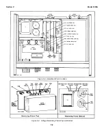
Each operating control and connector located on
the 3300A is identified and described in Figure 3-1. The
description of each component is keyed to an illustration
of that component.
3-5.
TURN ON PROCEDURE.
NOTE
One of the plug-ins must be in place
and locked in before the 3300A is
turned on. To remove a plug-in, turn
off the 3300A and turn the LOCK knob
fully counter-clockwise. This unlocks
the plug-in and pushes it part way out
for ease of removal. To install a plug-
in, turn the LOCK knob fully counter -
clockwise and push into place in the
3300A until it hits the stop, then turn
the LOCK knob fully clockwise.
3-6.
To turn on the Model 3300A, proceed as follows:
(Refer to Figure 3-1).
a.
Set 115/230 V slide switch (1) to line voltage
to be used, and check for proper value fuse
(.6 amp slow-blow for 115 volt operation, .4
amp slow-blow for 230 volt operation).
b.
Connect Power Input Jack (2) to the ac line
voltage with the power cord furnished with
instrument.
c.
Depress POWER button (3); ensure that
light in button illuminates.
3-7.
OPERATING INSTRUCTIONS.
NOTE
For small signal applications to obtain
optimum signal to noise performance,
use an external 20 dB attenuator.
3-8.
To operate the Model 3300A locally using the
FREQUENCY dial, proceed as follows: (See Figure 3-1).
a.
Select desired frequency by settings RANGE
Switch (4) and FREQUENCY Dial (5).
b.
Select desired function by setting CHANNEL
A and/or CHANNEL B Function Switch (7) or
(8). PLUG-IN position is used for plug-in
function(s).
c.
Set AMPLITUDE controls (9) for desired
output level at the OUTPUT connectors(10)
or (11).
3-9.
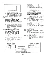
To control the frequency of the Model 3300A
externally (remotely) proceed as follows:
a.
Remove FREQ DIAL-to-FREQ CONTROL
shorting bar (14).
CAUTION
VOLTAGE APPLIED TO FREQ
CONTROL BNC SHOULD BE LIMITED
TO A VALUE B0.3 AND -15
VOLTS. VOLTAGES OUTSIDE THIS
RANGE WILL DAMAGE THE
INSTRUMENT.
b.
Apply a negative dc voltage from -0.5 to -10
volts to the FREQUENCY CONTROL BNC
(12).
NOTE
-0.5 to -10 volts will linearly control the
frequency over one decade of range
selected. A +0.3 to -10 volts will
linearly control the frequency over
50:1 range.
c.
Select desired frequency range and set
amplitude of externally applied voltage for
desired frequency.
d.
All 3300A controls except the FREQUENCY
dial are operated in the same manner as in
Paragraph 3-8.
3-10.
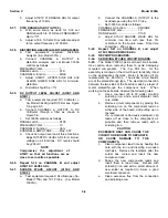
To dc offset the output function of the 3300A with
either the 3301A or 3302A Plug-in, proceed as follows:
a.
Remove CKT GND-to-OUTPUT GND
shorting bar (15).
CAUTION
DO NOT EXCEED ± 25 V DC OFFSET
VOLTAGE BETWEEN OUTPUT
GROUND AND CIRCUIT GROUND.
b.
Connect the desired dc offset voltage, up to
3-1
Summary of Contents for 3300A
Page 31: ...Model 3300A Section VI Figure 6 1 3300A Top and Bottom Views 6 2 ...
Page 32: ...Model 3300A Section VI Figure 6 2 Oscillator Circuit Schematic A11 A13 and A14 6 3 ...
Page 33: ...Model 3300A Section VI Figure 6 4 Output Amplifiers Schematic A15 and A16 6 5 6 6 ...
Page 34: ...TM 11 6625 2495 14 P THIS PAGE CURRENTLY NOT AVAILABLE FOR DIGITIZATION PAGE Figure 6 3 6 4 ...
Page 35: ...Model 3300A Section VI Figure 6 5 Power Supply Schematic A12 and A11 6 7 6 8 ...
Page 36: ...Model 3300A Section VI Figure 6 6 J6 Plug In Receptacle 6 9 ...
Page 58: ...SECTION IV REMARKS REFERENCE REMARKS CODE A Visuals B Performance checks D 5 ...
Page 60: ......
Page 61: ...PIN 046175 000 ...