


Model 3300A
Section V
b.
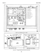
Connect the instruments as shown in Figure
5-2. Remove FREQ. DIAL-to-FREQ.
CONTROL shorting bar.
c.
Set 3300A controls as follows:
CHANNEL A function switch ......SINE
RANGE switch............................X10
CHANNEL A AMPLITUDE .........Max. CW
d.
Monitor frequency as power supply is varied
from 0 to -10 volts. Frequency should vary
over the decade, 10 to 100 cycles.
5-20.
CHANNEL B-A CHECK.
a.
Test equipment required: Oscilloscope (-hp-
Model 175A/1750B).
b.
Connect CHANNEL A OUTPUT to one
channel of the oscilloscope and CHANNEL
B OUTPUT to the other channel of the
oscilloscope.
c.
Set 3300A controls as follows:
CHANNEL A function switch ......SINE
CHANNEL B function switch ......-A
d.
The output of CHANNEL B should be a sine
wave, but 1800 out of phase with the output
of CHANNEL A.
5-21.
ADJUSTMENT AND CALIBRATION.
5-22.
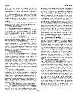
COVER REMOVAL.
When it is necessary to repair or adjust the Model
3300A, one or more covers will have to be removed. To
remove either the top or bottom cover, remove the two
phillips screws and slide the cover to the rear.
NOTE
Allow a 30-minute warm-up period
before making any adjustments.
5-23.
POWER SUPPLY ADJUSTMENTS.
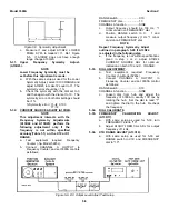
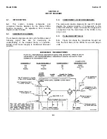
5-24.
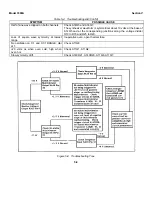
The adjustment and calibration procedures are
designed to adjust and calibrate the -hp- Model 3300A
and should be undertaken only if the performance
checks indicate the instrument does not meet
specifications. (See Figure 5-3 for adjustment
identification and indication.)
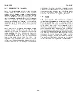
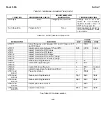
5-25.
The measurement points, adjustments and
voltage limits are given in Table 5-2. Refer to Figure 5-4
for convenient top and bottom chassis location for
monitoring supply voltage. Supplies should be adjusted
in the following order: -26. 5V, +26.5 V, -20 V, +20 V.
The supplies should be rechecked and, if necessary,
readjusted in the same order.
5-26.
POWER SUPPLY RIPPLE CHECK.
a.
Test equipment required: AC Voltmeter (-
hp- Model 400F/FL).
b.
With the AC Voltmeter, check the regulated
power supplies (i26. 5 V and +20.00 V) for
ripple.
c.
Ripple should be < 20 millivolts.
5-27.
POWER SUPPLY REGULATION CHECK.
a.
Test equipment required: DC Voltmeter (-
hp- Model 3440A/3443A) and Variable Line
Voltage Transformer.
b.
Apply power to the 3300Athroughthe
variable line voltage transformer.
c.
With the DC Voltmeter, check the regulated
power supplies as input voltage to the
3300A is varied from 103 to 127 Vac (207
to 253 Vac). Voltage limits are given in
Table 5-2.
5-28.
OVEN REGULATION.
a.
After 3300A has been on approximately 30
min, connect a DC Voltmeter between
circuit ground and collector of Q7 (Q9 on
instruments Serial prefixed: 519-, 533-,
609-, 616- and 622-.) Voltage noted should
be approximately 20 volts.
NOTE
This voltage will vary with oven
amplifier transistors.
b.
Turn 3300A off for approximately 1 minute,
then turn it on. Voltage should have
decreased to approximately 15 volts.
Voltage should then increase and
overshoot that noted in step a but in time
damp out to approximately 20 V.
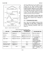
5-29.
FREQUENCY SYMMETRY ADJUST.
5-30.
Lower Frequency Symmetry Adj. (A13R22).
a.
Test equipment required: Electronic
Counter (-hp- Model 5245L with 5262A
Time Interval Plug-in).
b.
Set 3300A controls as follows:
RANGE Switch........................... X.1
CHANNEL A Function................ SQUARE
Output Attenuation ..................... Max. CW
FREQUENCY dial ...................... 1
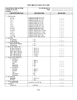
Table 5-2. Power Supply Adjustments
POWER
MEASUREMENT
ADJUSTMENTS
VOLTAGE
SUPPLY
POINT
LIMITS
+40
ANY RED WIRE (except on S2)
NONE
+40±3 V
-40
ANY VIOLET WIRE
NONE
-40±3 V
-26.5
ANY WHITE/VIOLET WIRE
A12R20
-26.5 ± 02 V
+26.5
ANY WHITE/RED WIRE
A12R7
+26.5 + .02 V
-20
ANY WHITE/BLACK/VIOLET WIRE
A12R26
-20.00+0.01 V
+20
ANY WHITE/BLACK/RED WIRE
A12R25
+20.00+. 01 V
5-3
Summary of Contents for 3300A
Page 31: ...Model 3300A Section VI Figure 6 1 3300A Top and Bottom Views 6 2 ...
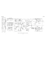
Page 32: ...Model 3300A Section VI Figure 6 2 Oscillator Circuit Schematic A11 A13 and A14 6 3 ...
Page 33: ...Model 3300A Section VI Figure 6 4 Output Amplifiers Schematic A15 and A16 6 5 6 6 ...
Page 34: ...TM 11 6625 2495 14 P THIS PAGE CURRENTLY NOT AVAILABLE FOR DIGITIZATION PAGE Figure 6 3 6 4 ...
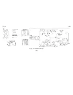
Page 35: ...Model 3300A Section VI Figure 6 5 Power Supply Schematic A12 and A11 6 7 6 8 ...
Page 36: ...Model 3300A Section VI Figure 6 6 J6 Plug In Receptacle 6 9 ...
Page 58: ...SECTION IV REMARKS REFERENCE REMARKS CODE A Visuals B Performance checks D 5 ...
Page 60: ......
Page 61: ...PIN 046175 000 ...