background image

Section V

Model 3300A

jumper location).  If 3300A operation is normal with this
plug mated with J6, the trouble is in the plug-in unit.

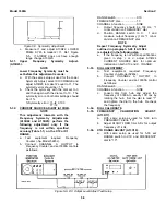
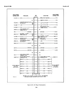
Figure 5-7.  Malfunction Isolating Plug

5-56.

PRECAUTIONS.

5-57.

In the event the -20 volt supply is inoperative, the

oven heater should be disabled while troubleshooting.  A
point to disable the oven is to disconnect the smaller
diameter red wire (26 gage) from XA12 Pin 1.  The larger

diameter redwire (22 gage) should be left connected to
XA12 Pin 1.  When the -20 volt power supply is left out,
the oven remains in full heat condition.  Thermal fuse
A11F1 will melt and open if this heat condition exists for
any extended period.

5-58.

When troubleshooting Power Supply Assembly,

remove the Output Amplifier Assemblies A15 and A16.

5-59.

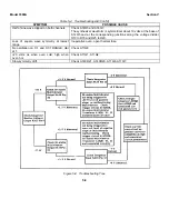
TROUBLESHOOTING TREE.

5-60.

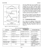
In the event of a malfunction which causes the

oscillatory system to cease functioning; the output of the
triangle integrator emitter follower would most likely
stabilize at either one of voltages as indicated in Figure
5-8.  Approxi25 volts is the upper limit of the
positive slope, and -2.5 volts is the lower

Table 5-4.  Troubleshooting Aid

SYMPTOM

POSSIBLE CAUSE

No output either channel.  Power Lamp lit.

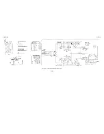
Use Figure 5-8 Troubleshooting Tree.

Output on only one channel.

Check applicable amplifier board A15
CHANNEL A or A16 CHANNEL B.

Frequency incorrect.  Specific range.

Check feedback capacitor of effected
range on Triangle Integrator A12; for
example, Range X100 check C10, C11,
and C12.

Two of the three functions normal, only

Check input resistor of missing function;

one channel effected.

on amplifier assembly; for example, no
SINE on CHANNEL A.  Check A15R1.

Frequency and symmetry incorrect at

Check oven heating voltage J6 pin 42

low end of dial, all ranges.

20 volts.

Frequency will not vary with FREQ dial.

Check Freq shorting bar rear chassis;
A11Q5 and associated circuit parameters.

No sync output.

Check A14C7, A14R46 and A14R48.

Power supply voltage incorrect.

Begin troubleshooting by substituting a
well-regulated 12.1 volt source for A11CR1.
Remove Output Amplifiers when trouble-
shooting Power Supply.

Frequency out of tolerance on 1 or 2

Change A11Q8.  Use caution in soldering

ranges which are not adjacent.

and use a clip-on heat sink.

Distortion at 100 kHz.

Check A13Q1.

Dc level off on square wave.

Check A14CR18 for open.

Symmetry erratic at low frequencies.

Check A14Q8.

Lower half of sine wave clipped on one

Check A15Q5 or A16Q5.

channel only.
Will not oscillate.

Check Triangle Integrator A13Q1 thru
A13Q3.

5-8

Summary of Contents for 3300A

Page 1: ...TOR S ORGANIZATIONAL DIRECT SUPPORT AND GENERAL SUPPORT MAINTENANCE MANUAL INCLUDING REPAIR PARTS AND SPECIAL TOOLS LISTS FOR GENERATOR SIGNAL SG 747 U HEWLETT PACKARD 3300A NSN 6625 00 118 6736 HEADQUARTERS DEPARTMENT OF THE ARMY 4 AUGUST 1980 ...

Page 2: ... CANNOT TURN OFF THE ELECTRICAL POWER PULL PUSH OR LIFT THE PERSON TO SAFETY USING A DRY WOODEN POLE OR A DRY ROPE OR SOME OTHER INSULATING MATERIAL SEND FOR HELP AS SOON AS POSSIBLE AFTER THE INJURED PERSON IS FREE OF CONTACT WITH THE SOURCE OF ELECTRICAL SHOCK MOVE THE PERSON A SHORT DISTANCE AWAY AND IMMEDIATELY START ARTIFICIAL RESUSCITATION 5 1 2 3 4 5 ...

Page 3: ... the products of decomposition are toxic and irritating Since TRICHLOROTRIFLUOROETHANE dissolves natural oils prolonged contact with skin should be avoided When necessary use gloves which the solvent cannot penetrate If the solvent is taken internally consult a physician immediately WARNING When the output ground is floated above Power Line Ground all BNC connectors will be at the offset voltage a...

Page 4: ... Forms 2028 2 in back of your manual use the standard DA Form 2028 Recommended Changes to Publications and Blank Forms and forward it to the Commander US Army Communications and Electronics Materiel Readiness Command ATTN DRSEL ME MQ Fort Monmouth NJ 07703 In either case a reply will be furnished direct to you TABLE OF CONTENTS SECTION Page 0 INTRODUCTION 0 1 0 1 SCOPE 0 1 0 2 INDEXES OF PUBLICATI...

Page 5: ...te Frequency Control Check 5 2 5 20 Channel B A Check 5 3 5 21 Adjustment and Calibration 5 3 5 22 Cover Removal 5 3 5 23 Power Supply Adjustments 5 3 5 26 Power Supply Ripple Check 5 3 5 27 Power Supply Regulation Check 5 3 5 28 Oven Regulation 5 3 5 29 Frequency Symmetry Adjust 5 3 5 32 Current Source Adjust 5 5 5 33 Dial Adjustment 5 5 5 34 Dial Calibrate 5 5 5 38 Distortion Adjust 5 6 5 39 DC ...

Page 6: ...e Monitoring Points Top and Bottom 5 4 5 5 Symmetry Adjustment 5 5 5 6 DC Output Level Adjust Test Setup 5 5 Number Page 5 7 Malfunction Isolating Plug 5 8 5 8 Troubleshooting Tree 5 9 5 9 Normal Oscillator Wave Forms 5 10 6 1 3300A Top and Bottom Views 6 2 6 2 Oscillator Circuit Schematic A11 A13 and A14 6 3 6 3 Range Switch Connections to Plug In Unit 6 4 6 4 Output Amplifiers Schematic A15 and ...

Page 7: ...ll out and forward DD Form 6 Packaging Improvement Report as prescribed in AR 735 11 2 NAVSUPINST 4440 127E AFR 400 54 MCO 4430 3E and DSAR 4140 55 c Discrepancy in Shipment Report DISREP SF 361 Fill out and forward Discrepancy in Shipment Report DISREP SF 361 as prescribed in AR 55 38 NAVSUPINST 4610 33B AFR 75 18 MCO P4610 19C and DSAR 4500 15 0 4 REPORTING OF EQUIPMENT IMPROVEMENT RECOMMENDATIO...

Page 8: ...QUENCY RESPONSE 1 0 01 Hz to 10 open circuit 5 µsec duration Sync pulse kHz 3 10 kHz to 100 kHz on the X10K occurs at crest of sine and triangle wave range DC STABILITY Drift 0 25 6 of peak to peak DIAL ACCURACY 1 of maximum dial setting amplitude over a period of 24 hours After 30 1 minor division 0 01 Hz to 10 kHz 2 of minute warmup maximum dial setting 2 minor divisions 10 kHz to 100 kHz T C 0 ...

Page 9: ...re than one decade by applying a 0 3 to 10 volts to the FREQUENCY CONTROL BNC A 0 3 to 10 V input will linearly control the frequency over approximately a 50 1 range 1 7 OUTPUT SYSTEM 1 8 The hp Model 3300A has two completely separate output channels Each output is dc coupled and can be fully floating with respect to power line ground An internal shield reduces radiated interference and provides c...

Page 10: ...A is fully transistorized therefore no special cooling is required However the instrument should not be operated where the ambient temperature exceeds 55 C 131F 2 12 BENCH MOUNTING 2 13 The Model 3300A is shipped with plastic feet and tilt stand in place ready for use as a bench instrument 2 14 RACK MOUNTING 2 15 The Model 3300A may be rack mounted by using the 5 Rack Mount Kit hp Part No 5060 077...

Page 11: ...tary switch which selects the desired OUTPUT 10 8 CHANNEL B Function Switch S5 a five position rotary switch which selects the desired OUTPUT 11 9 AMPLITUDE Controls R12 and R9 attenuators which vary the output level of the respective channels 10 and 11 OUTPUT Connectors J2 and J3 BNC jacks for connection to the respective outputs of the function generator 12 FREQUENCY CONTROL J5 a BNC jack for ap...

Page 12: ...s to obtain optimum signal to noise performance use an external 20 dB attenuator 3 8 To operate the Model 3300A locally using the FREQUENCY dial proceed as follows See Figure 3 1 a Select desired frequency by settings RANGE Switch 4 and FREQUENCY Dial 5 b Select desired function by setting CHANNEL A and or CHANNEL B Function Switch 7 or 8 PLUG IN position is used for plug in function s c Set AMPLI...

Page 13: ...uld be shorted together 15 c If more than 25 V dc offset is desired short CKT GND OUTPUT GND and SHIELD GND together 15 Up to 250 V dc may be applied between this common ground and PWR LINE GND WARNING WHEN THE OUTPUT GROUND IS FLOATED ABOVE POWER LINE GROUND ALL BNC CONNECTORS WILL BE AT THE OFFSET VOLTAGE 3 2 ...

Page 14: ...ge comparator multivibrator changes state and again reverses the direction of current at the input of the integrator and causes the output of the integrator to rise This rise continues until the voltage comparator multivibrator again changes state thus completing the cycle 4 7 The frequency control network governed internally by the FREQUENCY Dial or externally through the FREQUENCY CONTROL determ...

Page 15: ...R45 provide a low resistive path to ensure rapid rise and fall time of the square wave in the event the capacitance of the load is high When the positive slope of the triangle wave reaches 20 volts A14CR13 is turned on A14Q9 is then turned on which turns A14Q10 off The rise in the collector voltage of A14Q10 is coupled through emitter follower A14Q11 and through A14CR20 and A14CR21 into the emitte...

Page 16: ...bias is determined by the sum of the forward biased base emitter diode voltage of Q1 and Q2 in addition to the voltage drop across the R5 R6 combination When this forward bias increases to a level sufficient to allow the diodes to conduct any increase in the collector current of Q4 will pass through the diodes and not enter the base of Q2 This in thru limits the maximum current in the series regul...

Page 17: ...stment and Calibration Repair DC Voltmeter Accuracy 1 F S Adjustment and hp 3440A Digital Volt Range 10 mV to 50 V Calibration Repair meter with Plug in hp Input Impedance 10 MΩ Model 3443A Resistor 600 ohms Performance Checks hp Part No 0730 0010 1 4 watt 5 Resistor 50 ohms Performance Checks hp Part No 0683 5105 1 4 watt 5 Resistor 20 K Adjustment and hp Part No 0686 2035 1 4 watt Calibration 5 ...

Page 18: ...s be 1 or 2 minor divisions at any point on the dial 5 7 DISTORTION CHECK a Test equipment required Distortion Analyzer hp Model 331A b Connect the OUTPUT of CHANNEL A to distortion analyzer and set 3300A controls as follows FREQUENCY dial 10 RANGE switch X1K CHANNEL A function switch SINE CHANNEL A AMPLITUDE control mid position c Distortion should be less than 1 d Position the RANGE switch to X1...

Page 19: ...dial 10 RANGE switch X10K c Verify Rise and fall time 250 nano sec Sag 1 Overshoot full output 5 Symmetry error 1 5 18 SYNC OUTPUT a Test equipment required Oscilloscope hp Model 175A 1750B and 10 1 Probe hp Model 10001A b Connect SYNC OUTPUT to oscilloscope and set 3300A controls as follows FREQUENCY dial 10 RANGE switch X1K c Pulse should be 10 volts peak to peak and 5 microsecond duration 5 19 ...

Page 20: ...The supplies should be rechecked and if necessary readjusted in the same order 5 26 POWER SUPPLY RIPPLE CHECK a Test equipment required AC Voltmeter hp Model 400F FL b With the AC Voltmeter check the regulated power supplies i26 5 V and 20 00 V for ripple c Ripple should be 20 millivolts 5 27 POWER SUPPLY REGULATION CHECK a Test equipment required DC Voltmeter hp Model 3440A 3443A and Variable Lin...

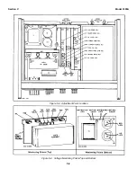
Page 21: ...Section V Model 3300A Figure 5 3 Adjustment Point Location Figure 5 4 Voltage Monitoring Points Top and Bottom 5 4 ...

Page 22: ...GE switch X10 FREQUENCY dial 10 CHANNEL A function SINE c Output frequency should be 100 Hz 1 minor division on FREQUENCY dial d Position RANGE switch to X 1 and measure output frequency 1 Hz 1 minor division on FREQUENCY dial NOTE Repeat Frequency Symmetry Adjust outlined in paragraph 5 29 if A13R24 is adjusted in the following step e If the frequency is not within specifications given in step c ...

Page 23: ...unction SQUARE FREQUENCY dial 10 RANGE switch X10K d Adjust A15C2 SQUARE WAVE ADJ for minimum rise time with less than 5 overshoot on the square wave Rise time should be 250 n sec 5 42 Repeat 5 41 on CHANNEL B and adjust A16C2 SQUARE WAVE ADJ 5 43 REPAIR PROCEDURES 5 44 SERVICING ETCHED CIRCUIT BOARDS 5 45 The Model 3300A has six etched circuit boards Use caution when removing them to avoid damagi...

Page 24: ...determined by the following formula Ccorrection C feedback Freq desired Freq X100 desired Freq Example X1K range inaccurate Freq of 9 8 kHz Range X1K dial 10 Ccorrection 0 011 µF 9 8K 10K X100 10K 0 011 µF 00137 µF 8 5 50 TROUBLESHOOTING PROCEDURE 5 51 This section contains procedures designed to assist in the isolation of a malfunction These procedures are based on a systematic analysis of the in...

Page 25: ...USE No output either channel Power Lamp lit Use Figure 5 8 Troubleshooting Tree Output on only one channel Check applicable amplifier board A15 CHANNEL A or A16 CHANNEL B Frequency incorrect Specific range Check feedback capacitor of effected range on Triangle Integrator A12 for example Range X100 check C10 C11 and C12 Two of the three functions normal only Check input resistor of missing function...

Page 26: ...s at the base of A14Q5 and at the corresponding junctions along the voltage divider R10 to R15 and R25 to R20 Loss of square wave symmetry at lowest range Inoperative oven open thermal fuse No oscillation on X 1 and X 01 RANGE dial at 1 Check A11Q8 20 volts ok when oven cold high when oven hot Check A11Q1 A11Q2 Slow symmetry drift Check A14CR21 A14CR20 A11Q6 A11Q7 Figure 5 8 Troubleshooting Tree 5...

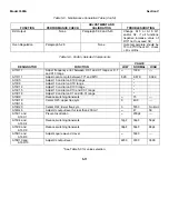
Page 27: ... 5 62 TROUBLESHOOTING TABLES 5 63 Table 5 4 gives additional information to assist in the isolation of a malfunction Symptoms and possible causes are listed Table 5 5 Maintenance Correlation Table lists various 3300A functions and gives the corresponding performance checks and adjustments Table 5 5 Maintenance Correlation Table ADJUSTMENT AND FUNCTION PERFORMANCE CHECK CALIBRATION TROUBLESHOOTING ...

Page 28: ... oven temp to between 70º and 80ºC 8 2K 8 87K 9 09K A13C5 Adjust 10 on dial on X10K range A13C9 Adjust 10 on dial on X1K range A13C12 Adjust 10 on dial on X100 range A13C15 Adjust 10 on dial on X10 and X0 1 range A13C18 Adjust 10 on dial on X1 and X0 01 range A13R9 Reduce switching transients 15 A13R18 A13R19 Center R23 upper freq sym 0 49 9 A13R20 Center R22 lower freq sym 3 5760 No limit A14R46 ...

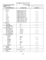
Page 29: ...een 9 9 kHz and 10 1 kHz _______ 1 x 10K between 8 kHz and 12 kHz _______ 10 x 10K between 98 kHz and 102 kHz _______ 2 Distortion X1K Range 1 _______ X10K Range 3 _______ 3 Frequency Response X 01 thru X1K Range 1 _______ X10K Range 3 _______ 4 Maximum Output Level No load Channel A 35 V p p _______ No load Channel B 35 V p p _______ 600ê load Channel A 16 V p p _______ 600ê load Channel B 16 V p...

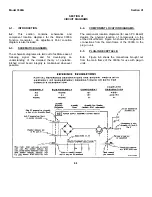
Page 30: ... flow and for developing an understanding of the detailed theory of operation Etched circuit board integrity is maintained whenever possible 6 4 COMPONENT LOCATION DIAGRAMS The component location diagrams for each PC Board depicts the physical location of components on the etched circuit board Figure 6 3 shows the range switch connections from the main frame of the 3300A to the plug in unit 6 5 PL...

Page 31: ...Model 3300A Section VI Figure 6 1 3300A Top and Bottom Views 6 2 ...

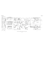
Page 32: ...Model 3300A Section VI Figure 6 2 Oscillator Circuit Schematic A11 A13 and A14 6 3 ...

Page 33: ...Model 3300A Section VI Figure 6 4 Output Amplifiers Schematic A15 and A16 6 5 6 6 ...

Page 34: ...TM 11 6625 2495 14 P THIS PAGE CURRENTLY NOT AVAILABLE FOR DIGITIZATION PAGE Figure 6 3 6 4 ...

Page 35: ...Model 3300A Section VI Figure 6 5 Power Supply Schematic A12 and A11 6 7 6 8 ...

Page 36: ...Model 3300A Section VI Figure 6 6 J6 Plug In Receptacle 6 9 ...

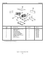
Page 37: ...VER REAR SIDE 2 5000 0732 5 COVER FRONT SIDE 2 5000 0733 6 COVER TOP ASSEMBLY 1 5060 0739 7 COVER BOTTOM ASSEMBLY 1 5060 0751 8 HANDLE SIDE ASSEMBLY 2 5060 0222 9 RETAINER HANDLE ASSEMBLY 2 5060 0766 10 ASSEMBLY FOOT 5 5060 0767 11 STAND TILT 1 1490 0030 12 PLATE FLUTED AL 2 5000 0051 See backdating information in Appendix C Figure 7 1 Modular Cabinet Parts 7 0 ...

Page 38: ... slide Al aluminum impg impregnated seconds SPDT single pole double A ampere a incd incandescent nsr not separately replace throw Au gold ins insulation ed able SPA T single pole single throw C capacitor kÒ kilohm s 10 3 ohms Ò ohm s Ta tantalum cer ceramic obd order by description TC temperature coefficient coef coefficient kHz kilohertz 10 3 hertz OD outside diameter TiO2 titanium dioxide com co...

Page 39: ...1 8 W 19701 MF5C T O obd A11R7 0757 0283 2 R fxd prec met flm 2 kΩ 1 1 8 W 19701 MF5C T O obd A11R8 0698 3482 2 R fxd prec met flm 224K 1 4 1 2 W 75042 CEC T O obd A11R9 A1R10 0698 3355 1 R fxd prec met flm 1 5 MΩ 1 4 1 2 W 75042 CEC T O obd A11R11 0757 0861 1 R fxd prec met flm 130 kΩ 1 1 2 W 75042 CEC T O obd A11R12 0698 6683 1 R fxd prec met flm 169K 0 25 1 4 W 19701 MF6C T 8 obd A11R13 0757 04...

Page 40: ... T O obd A12R20 2100 1434 1 R var prec comp 1K 30 1 8 W 71450 XQS 200 obd A12R21 0683 3625 R fxd comp 3 6K 5 1 2 W 75042 CEC T O obd A12R22 0757 0817 2 R fxd prec met flm 750Ω 1 1 2 W 75042 CEC T O obd A12R23 A12R24 0683 1035 1 R fxd prec comp 10K 5 1 4 W 01121 CB 1035 A12R25 2100 1757 2 R var ww lin 500Ω 10 1 2 W 75042 Type 506 obd A12R26 2100 1759 2 R var ww lin 2K 10 1 2 W 75042 Type 506 obd A1...

Page 41: ...1 4 W 91637 MFF 1 8 32 obd A13R21 0757 0813 1 R fxd met flm 475Ω 1 0 1 2 W 91637 MFF 1 2 10 T 1 A13R22 2100 1759 R var ww lin 2K 10 1 2 W 75042 Type 506 obd A13R23 2100 1702 1 R var ww 100Ω 10 1 W 88874 2600 Series obd A13R24 2100 1758 1 R var ww lin 1K 10 1 2 W 75042 Type 506 obd A13R25 0683 1515 1 R fxd comp 150Ω 5 1 4 W 01121 CB 1515 1205 0033 Heat dissipator semi conductor for Q1 05820 NF 207 ...

Page 42: ... 00 KΩ 1 1 8W 19701 MF5C T O obd A14R21 0698 4447 R fxd prec met flm 280Ω 1 1 8W 75042 CEA T O obd A14R22 0698 3439 R fxd prec met flm 178Ω 1 1 8W 75042 CEA T O obd A14R23 0698 4410 R fxd prec met flm 137Ω 1 1 8W 75042 CEA T O obd A14R24 0698 4396 R fxd prec met flm 80 6Ω 1 1 8W 19701 MFSC T O obd A14R25 0757 0394 R fxd prec met fin 51 1Ω 1 1 8W 19701 MF5C T O obd A14R26 0698 3558 R fxd 4 02K 1 1 ...

Page 43: ...2 W 19701 MF7C T O obd A15R4 0698 3348 2 R fxd prec met flm 4 64K 1 1 2 W 75042 CEC T O obd A15R5 0757 0832 R fxd prec met flm 4 75K 1 1 2 W 75042 CEC T O obd A15R6 0683 4705 R fxd comp 47Ω 5 1 4 W 01121 CB 4705 A15R7 2100 0361 2 R var comp 2K 30 1 8 W 71450 XQS 200 obd A15R8 0757 0041 2 R fxd prec met flm 11 3K 1 1 2 W 75042 CEC T O obd A15R9 0698 3352 2 R fxd prec met flm 11 5K 1 1 2 W 75042 CEC...

Page 44: ...11 0686 6215 4 R fxd comp 620Ω 5 1 2 W 01121 EB6215 R12 2100 1548 R var comp molded C attenuator 600Ω 12687 53M obd 20 5 W R13 R14 0686 6215 R fxd 620Ω 5 1 2 W 01121 EB6215 R15 Not assigned R16 R17 0699 0002 2 R fxd comp 6 8Ω 10 1 2 W 01121 EB68G1 S1 3101 0100 1 Switch pushbutton lighted SPDT 2 amp at 87034 SW 624 109 125 vacw POWER DS1 1450 0106 1 Lamp neon 87034 A1C S2 3101 1234 1 Switch slide D...

Page 45: ...r 10 for Q3 thru Q7 000LB 294834 03300 84401 1 Kit accessory hp 0370 0160 1 Knob dial round 1 58 diam black hp FREQUENCY DIAL 0370 0025 1 Knob round 3 4 diam black for 1 4 diam hp shaft VERNIER 0370 0077 3 Knob skirted bar 5 8 diam black for 1 4 hp diam shaft RANGE and FUNCTION 0370 0133 2 Knob skirted 5 8 diam black for 1 4 hp diam shaft AMPLITUDE 03300 01201 1 Latch plug in hp 03300 90005 1 Manu...

Page 46: ...CB2415 01121 5905 00 435 1718 30D107G025DD2DSM 56289 5910 00 082 5119 CB2425 01121 5905 00 911 3811 342014 75915 5920 00 881 4636 CB3015 01121 5905 00 686 3122 353 18 06 001 71785 5940 00 997 5693 CB3035 01121 5905 00 909 3954 45R1 83186 5905 00 893 1151 CB3335 01121 5905 00 909 3967 5C13C 56289 5910 00 809 5484 CB3625 01121 5905 00 104 8369 56 590 65 3B 02114 5950 00 784 0475 CB3925 01121 5905 00...

Page 47: ... Prod Inc Mt View Operations 15566 Amprobe Inst Corp Lynbrook N Y 02771 Vocaline Co of America Inc Mountain View Calif 15631 Cabletronics Costa Mesa Calif Old Saybrook Conn 07700 Technical Wire Products Inc Cranford N J 15772 Twentieth Century Coil Spring Co 02777 Hopkins Engineering Co San Fernando Calif 07829 Bodine Elect Co Chicago III Santa Clara Calif 02875 Hudson Tool Die Co Newark N J 07910...

Page 48: ...42 International Resistance Co Philadelphia Pa 82170 Fairchild Camera Inst Corp Space Defense 60741 Triplett Electrical Inst Co Bluffton Ohio 75263 Keystone Carbon Co Inc St Marys Pa System Div Paramus N J 61775 Union Switch and Signal Div of 75378 CTS Knights Inc Sandwich Ill 82209 Maguire Industries Inc Greenwich Conn Westinghouse Air Brake Co Pittsburgh Pa 75382 Kulka Electric Corporation Mt Ve...

Page 49: ...er Co Consumer Ind Plastics 95263 Leecraft Mfg Co Inc Long Island N Y 99928 Branson Corp Whippany N J Prod Div Passaic N J 95265 National Coil Co Sheridan Wyo 99934 Renbrandt Inc Boston Mass 90970 Bearing Engineering Co San Francisco Calif 95275 Vitramon Inc Bridgeport Conn 99942 Hoffman Electronics Corp 91146 ITT Cannon Elect Inc Salem Div Salem Mass 95348 Gordos Corp Bloomfield N J Semiconductor...

Page 50: ...Prentice St Louis 63144 Syracuse 13211 TWX 710 381 7573 Englewood 80110 ILLINOIS Tel 314 962 5000 Tel 315 454 2486 Tel 303 771 3455 5500 Howard Street TWX 910 760 1670 TWX 710 541 0482 TEXAS FOR U S AREAS NOT TWX 910 935 0705 Skokie 60076 P O Box 1270 LISTED Tel 312 677 0400 NEW JERSEY NORTH CAROLINA 201 E Arapaho Rd Contact the regional office near TWX 910 223 1613 W 120 Century Road P O Box 5188...

Page 51: ...32 2024YHP Tel 511027 512927 Nairobi Box 6487 Cable HE I NAMI Blue Star Ltd Cable YHPMARKET TOK 23 724 Cable COOPERATOR Karachi Tel 25670 26803 68206 58196 Luanda 23 24 Second Line Beach Cable ARJAYTEE Nairobi Cable TELECTRA Luanda ETHIOPIA Madras 1 India KENYA PHILIPPINES African Salespower Agency Tel 2 39 55 R J Tilbury Ltd Electromex Inc THAILAND AUSTRALIA Private Ltd Co Telex 379 P O Box 2754 ...

Page 52: ...A16R28 with pieces of wire CHANGE 4 Replace A13R25 with a piece of wire CHANGE 5 For instruments with serial number 939 04925 and below change the following part numbers J1 should be 1251 0148 W1 should be 8120 0078 Rear Panel should be 03300 00202 These parts are not directly interchangeable with the ones listed in Table 7 1 If any one is changed all should be changed CHANGE 6 RECOMMENDED INSTRUM...

Page 53: ...intenance Manual Including Repair Parts and Special Tools Lists Volt meter Digital AN GSM 64B NSN 6625 00 022 7894 Including Plug In Electronic Test Equipment PL 1370 GSM 64B NSN 6625 00 137 8366 TM 11 6625 700 14 1 Operator Organizational Direct Support and General Support and Depot Maintenance Manual Including Repair Parts and Special Tools Lists Digital Readout Electronic Counter AN USM 207A Se...

Page 54: ...t or assembly in a manner to allow the proper functioning of the equipment or system h Replace The act of substituting a serviceable like type part subassembly or module component or assembly for an unserviceable counterpart i Repair The application of maintenance services inspect test service adjust align calibrate replace or other maintenance actions welding grinding riveting straightening facin...

Page 55: ...those common tool sets not individual tools and special tools test and support equipment required to perform the designated function f Column 6 Remarks Column 6 contains an alphabetic code which leads to the remark in section IV remarks which is pertinent to the item opposite the particular code D 4 Tool and Test Equipment Requirements Sec III a Tool or Test Equipment Reference Code The numbers in...

Page 56: ... A11 Test 1 0 1 5 12 14 Repair 1 0 15 16 Replace 5 15 16 02 Power Supply Assembly A12 Test 1 0 1 5 12 14 Repair 1 0 15 16 Replace 5 15 16 03 Antegrator Assembly A13 Test 1 0 1 5 12 14 Repair 1 0 15 16 Replace 5 15 16 04 Synthesizer and Voltage A14 Test 1 0 1 5 Comparator Assembly 12 14 Repair 1 0 15 16 Replace 5 15 16 05 Output Amp Assembly A15 Test 1 0 1 5 12 14 Repair 1 0 15 16 Replace 5 15 16 0...

Page 57: ... 5 H P 0730 0010 or equivalent 7 H D Resistor 50 drm 25 watt 5 H P 0683 5105 or equivalent 8 H D Resistor 20K OHM 25 watt 5 H P 0686 2035 or equivalent 9 H D Capacitor 1 micro f 50V H P 0160 0859 or equivalent 10 H D Variable Line Voltage Transformer CN 16 U 5950 00 235 2086 11 H D D C Power Supply PP 6647 U HP 723A 6130 00 171 0801 12 H D A C Voltmeter KE 459 U 6625 00 329 0457 13 H D Printed Cir...

Page 58: ...SECTION IV REMARKS REFERENCE REMARKS CODE A Visuals B Performance checks D 5 ...

Page 59: ...NSCOM 2 Army Dep 1 except TRADOC 2 SAAD 30 DARCOM 1 TOAD 14 TECOM 2 SHAD 2 OS Maj Comd 2 USA Dep 1 USACC 2 Sig See USA Dep 1 HISA Ft Monmouth 21 Units org under fol TOE Armies 1 2 copies each unit USASIGS 10 29 207 Svc Colleges 1 29 610 Ft Richardson CERCOM Ofc 1 1 copy each unit Ft Carson 5 29 134 Ft Gillem 10 29 136 ARNG None USAR None For explanation of abbreviations used see AR 310 50 U S GOVE...

Page 60: ......

Page 61: ...PIN 046175 000 ...

Page 62: ...e it They did not even scan it Why should they get your money Why are not letting you give those free manuals to your friends I am setting this document FREE This document was made by the US Government and is NOT protected by Copyright Feel free to share republish sell and so on I am not asking you for donations fees or handouts If you can please provide a link to liberatedmanuals com so that free...

Reviews: