Optical drive connector board
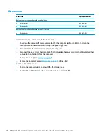
Description
Spare part number
Optical drive connector board
924990-001
Optical drive cable
924926-001
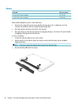
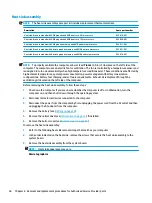
Before removing the optical drive connector board, follow these steps:
1.
Shut down the computer. If you are unsure whether the computer is off or in Hibernation, turn the
computer on, and then shut it down through the operating system.
2.
Disconnect all external devices connected to the computer.
3.
Disconnect the power from the computer by first unplugging the power cord from the AC outlet and then
unplugging the AC adapter from the computer.
4.
Remove the battery (see
).
5.
Remove the optical drive (see
), if installed.
6.
Remove the bottom cover (see
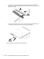
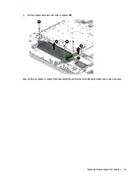
To remove the optical drive connector board:
1.
Disconnect the cable from the optical drive connector board (1).
2.
Remove the Phillips PM2.0×2.0 screw (2) that secures the optical drive connector board to the computer.
3.
Rotate the connector side of the board upward, and then pull the board up and out of the computer (3).
Reverse this procedure to install the optical drive board connector.
44
Chapter 6 Removal and replacement procedures for Authorized Service Provider parts
Summary of Contents for 255 G6
Page 1: ...HP 255 G6 Notebook PC Maintenance and Service Guide ...
Page 4: ...iv Safety warning notice ...
Page 8: ...viii ...
Page 12: ...4 Chapter 1 Product description ...
Page 24: ...16 Chapter 2 Components ...
Page 32: ...24 Chapter 3 Illustrated parts catalog ...
Page 77: ...e Remove the display hinges 3 Component replacement procedures 69 ...
Page 100: ...92 Chapter 10 Specifications ...
Page 110: ...102 Chapter 12 Power cord set requirements ...
Page 112: ...104 Chapter 13 Recycling ...

