c.
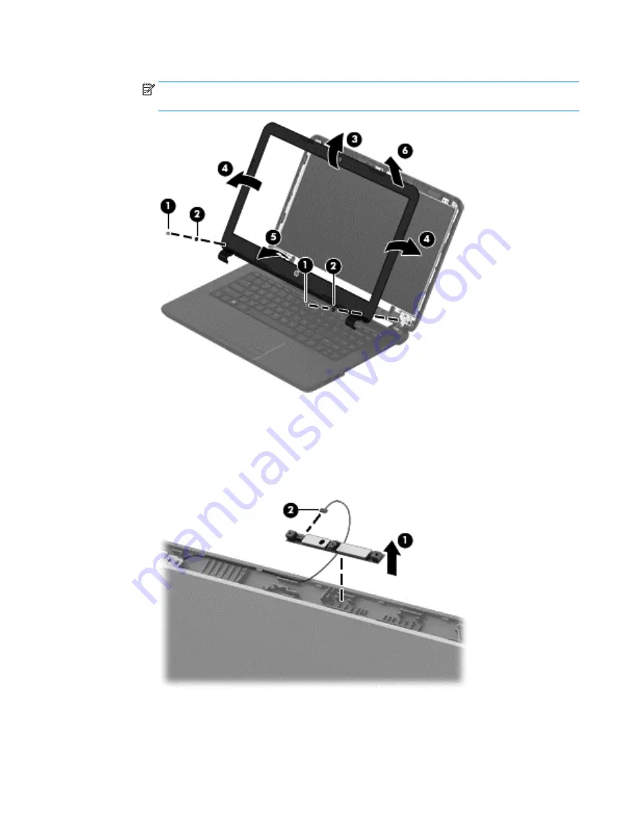
Remove the display bezel.
NOTE:
In this procedure, the display will NOT be connected to the computer, as shown in the
following image.
2.
To remove the webcam/microphone module:
a.
Position the display assembly with the top edge toward you.
b.
Disconnect the cable
(1)
from the module.
c.
Remove the webcam/microphone module
(2)
. (The module is attached to the display enclosure
with double-sided tape.)
3.
To remove the display panel:
a.
Remove the four Phillips PM2.0×3.0 screws that secure the display panel to the enclosure.
Component replacement procedures
79
Summary of Contents for 240 G3
Page 4: ...iv Safety warning notice ...
Page 14: ...6 Chapter 1 Product description ...
Page 26: ...18 Chapter 2 External component identification ...
Page 104: ...96 Chapter 4 Removal and replacement procedures ...
Page 108: ...100 Chapter 5 Using Setup Utility BIOS and HP PC Hardware Diagnostics UEFI in Windows 8 ...
Page 112: ...104 Chapter 6 Using Setup Utility BIOS and System Diagnostics in Windows 7 ...
Page 138: ...130 Chapter 12 Statement of Volatility ...
Page 142: ...134 Chapter 13 Power cord set requirements ...
Page 144: ...136 Chapter 14 Recycling ...
Page 148: ...140 Index ...


