6
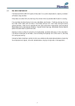
2.2
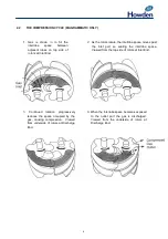
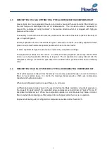
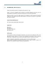
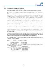
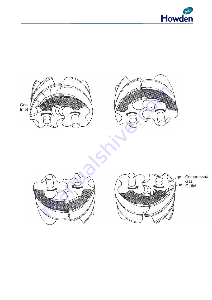
THE COMPRESSION CYCLE (DIAGRAMMATIC ONLY)
1. Gas is drawn in to fill the
interlobe
space
between
adjacent lobes on top side of
rotors at Inlet End.
2.
As the rotors rotate, the interlobe space moves past
the inlet port so sealing the interlobe space.
Viewed from the top side of rotors at Inlet End.
4.
When the interlobe space becomes exposed
to the outlet port the gas is discharged.
Viewed from the underside of rotors at
Discharge End.
3
.
Continued
rotation
progressively
reduces the space occupied by the
gas, causing compression. Viewed
from underside of rotors at Discharge
End.
Summary of Contents for WRV
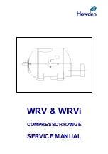
Page 1: ...WRV WRVi COMPRESSOR RANGE SERVICE MANUAL...
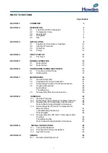
Page 3: ...2 SECTION 1 FOREWORD...
Page 5: ...4 HOWDEN SECTION 2 DESCRIPTION...
Page 10: ...9 SECTION 3 INSTALLATION...
Page 14: ...13 SECTION 4 FIRST START UP...
Page 16: ...15 SECTION 5 NORMAL OPERATION...
Page 18: ...17 SECTION 6 PROCEDURES DURING SHUTDOWN...
Page 20: ...19 SECTION 7 MAINTENANCE...
Page 33: ...32 SECTION 8 OVERHAUL...
Page 50: ...49 SECTION 9 SPECIAL INSTRUCTIONS...
Page 57: ...56 SECTION 10 SPARES...
Page 64: ...63 Printed in the UK Issue HCL September 2012 Howden Compressors Limited...

