


48
8.5
RE-ASSEMBLY WRV204, WRVi255, WRVi321 & WRVi365 COMPRESSORS AFTER OVERHAUL
(Continued)
Re-assemble the Outlet End Cover and Hydraulic Cylinder
Re-assembly as described per Section 7.5 for WRV204, WRVi255, WRVi321 & WRVi365
compressors.
Then proceed:
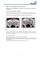
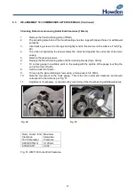
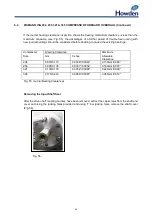
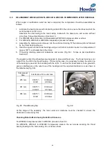
Re-assemble the Vi Cover WRVi255, WRVi321 & WRVi365 Compressors.
Pull Vi adjusting screw until the nut is against the inlet cover.
Refit the Vi adjuster cover ensuring new ‘O’ rings are in place and secure with fixing capscrews.
Refit circlip retaining ring to secure adjusting screw to cover.
NOTE:
Reset Vi adjusting screw to original position.
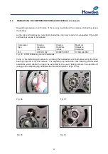
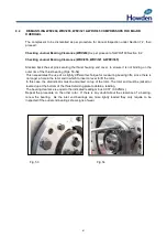
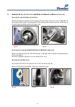
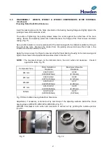
Re-assemble the Input Shaft Seal
Re-assemble the component in the following sequence:
1.
Enter the inlet balance piston ensuring it locates on the drive dowel.
2.
Lubricate the shaft seal and assemble to the rotor shaft, locate in the outward facing
dowel/driving pin of the inlet balance piston.
3.
Refit balance piston sleeve (WRV204 Only).
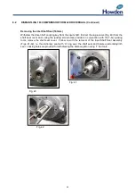
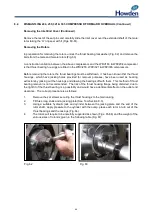
4.
Fit
new ‘O’ ring to stationary seat and fit to seal cover, ensuring seat locates on anti-rotation
dowel.
5.
Fit the seal cover with a new ‘O’ ring and secure with cap screws, tightening in a systematic
fashion to avoid tilting.
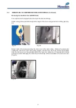
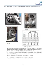
To complete the assembly, fit the coupling key and the compressor driven half coupling.
Summary of Contents for WRV
Page 1: ...WRV WRVi COMPRESSOR RANGE SERVICE MANUAL...
Page 3: ...2 SECTION 1 FOREWORD...
Page 5: ...4 HOWDEN SECTION 2 DESCRIPTION...
Page 10: ...9 SECTION 3 INSTALLATION...
Page 14: ...13 SECTION 4 FIRST START UP...
Page 16: ...15 SECTION 5 NORMAL OPERATION...
Page 18: ...17 SECTION 6 PROCEDURES DURING SHUTDOWN...
Page 20: ...19 SECTION 7 MAINTENANCE...
Page 33: ...32 SECTION 8 OVERHAUL...
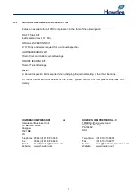
Page 50: ...49 SECTION 9 SPECIAL INSTRUCTIONS...
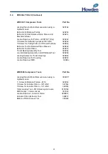
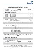
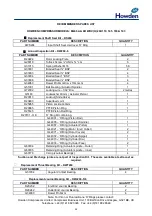
Page 57: ...56 SECTION 10 SPARES...
Page 64: ...63 Printed in the UK Issue HCL September 2012 Howden Compressors Limited...


