41
8.4
DISMANTLING WRV204, WRVi255, WRVi321 & WRVi365 COMPRESSORS FOR MAJOR
OVERHAUL
The compressor to be dismantled as per procedure for Annual Inspection under Section 7.2, then
proceed:
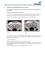
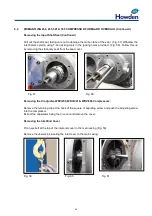
Checking Journal Bearing Clearance (WRV204)
As per procedure for WRV163 Section 8.2
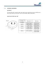
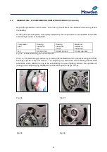
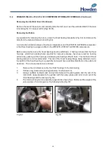
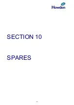
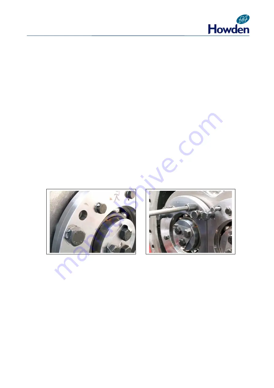
Checking Journal Bearing Clearance (WRVi255, WRVi321 & WRVi365)
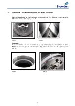
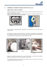
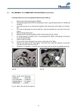
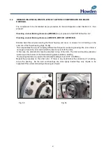
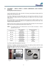
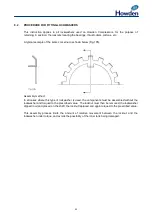
Slacken back the set pins securing the thrust housing end cover, to ensure it is not binding on the
outer rim of the thrust bearing (Figs. 53-54).
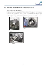
This necessitates the use of a slightly different technique for measuring bearing lifts, since there is
no longer a hole in the rotor end in which to insert a lever to lift the rotor.
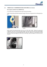
In this case, the dial indicator must be mounted on top of the rotor. The rotor end must be jacked or
levered up at the bottom of the thrust retaining plate to obtain a reading.
The bearing clearance is equal to the indicated reading minus 0.001” (0.025mm).
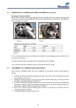
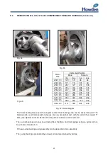
Repeat the procedure on the other rotor. If there is any doubt about the clearance of a bearing,
renew the bearing. As the inlet end bearings are more lightly loaded they only require to be
inspected if the outlet end bearings show signs of wear.
Fig. 53
Fig. 54
Summary of Contents for WRV
Page 1: ...WRV WRVi COMPRESSOR RANGE SERVICE MANUAL...
Page 3: ...2 SECTION 1 FOREWORD...
Page 5: ...4 HOWDEN SECTION 2 DESCRIPTION...
Page 10: ...9 SECTION 3 INSTALLATION...
Page 14: ...13 SECTION 4 FIRST START UP...
Page 16: ...15 SECTION 5 NORMAL OPERATION...
Page 18: ...17 SECTION 6 PROCEDURES DURING SHUTDOWN...
Page 20: ...19 SECTION 7 MAINTENANCE...
Page 33: ...32 SECTION 8 OVERHAUL...
Page 50: ...49 SECTION 9 SPECIAL INSTRUCTIONS...
Page 57: ...56 SECTION 10 SPARES...
Page 64: ...63 Printed in the UK Issue HCL September 2012 Howden Compressors Limited...


