15
Key
1. Burner control circuit switch
2. Burner run light
3. High fire run light
4. High temperature cutout light
5. Burner lockout light
6. Control thermostat adjustment
7. 2nd stage thermostat adjustment (where fitted)
8. 3rd stage thermostat adjustment (where fitted)
9. Limit thermostat manual reset
10. 3 Amp control circuit fuse
11. 6.3 Amp burner control circuit fuse
12. Space for optional burner hours run meter
13. Boiler flow temperature thermometer
14. Space for optional burner modulation controller
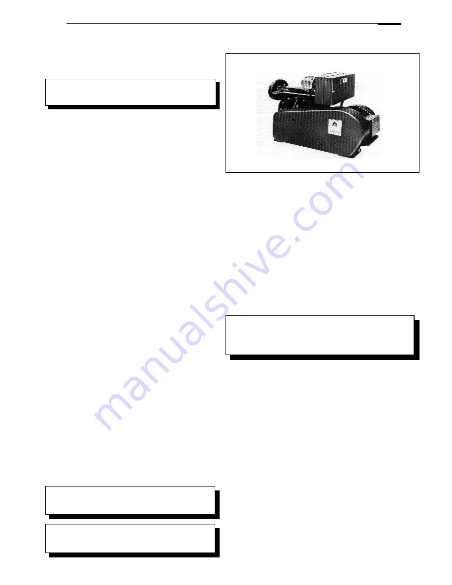
Gas Boosters
Installation - Gas Boosters
A booster is required when the gas pressure at the burner is
below the value specified by the burner manufacturer at the flow
rate attained at maximum burner rating.
Gas Regulations require that no more than 0.5" WG pressure
is lost due to pipe work resistance between the supply meter
and the gas inlet.
Booster Installation
It is usually preferably to locate the boosters as near as
possible to the burner served rather than close to the meter.
• Leave adequate access for servicing drive belts, fan
bearing assemblies, electrical motors and any acoustic
shroud.
• Ensure that the room in which the gas booster is to be
installed is well ventilated and free from dust.
• Before running the booster the machine should be cleaned
thoroughly, taking particular care to make sure that pulleys
and the belt are free from abrasive dust etc, which may
have settled on the machine during installation.
• If the booster is in the boilerhouse then the ventilation and
air inlet louvres for the boiler will also serve for the booster
to keep the ambient temperature satisfactory, providing the
full recommendations for free area and position are fulfilled.
• Standard boosters are designed to operate in ambient
temperatures not exceeding 40
o
C. When the booster is
housed separately to the boiler, ventilation must be
provided to keep the ambient temperature below this.
Ventilation openings in this case must be sized relative to
any heat emiters in the room and the effects of solar gain.
• The booster control enables the booster to work
automatically. Gas flow through the booster is required to
stop any excessive increase in operating temperature
and we recommend that the booster should only operate
in conjunction with the burner. Prolonged periods of
operation without any gas flow will cause an increase in
temperature, shortening the life of the booster and
increasing service frequency. If however the plant is
required to work under such conditions, consideration
should be given to the use of a purpose-designed bypass
to dissipate the excess heat and the installation of a twin
duty stand-by system to allow for regular inspection. Where
a stand-by booster is fitted, it should be operated regularly
or in rotation. If the booster is operating in rotation auto
cycling may have been installed as an option.
Important
If a vital function is served, install
a standby gas booster.
Do not test the fan chamber assembly by hydraulic
pressure: this practice will inevitably damage the fan
bearing assembly.
All booster assemblies are tested for gas tightness
by means of air at a pressure of 0.69 bar during
manufacture.
• Concrete floors should be sealed.
• Locate the booster on a firm, flat horizontal plinth approximately
450mm high to raise the unit to a convenient level.
• Noise attenuation and absence resonance are best obtained by
supporting the booster on anti-vibration mounts.
• For the same reasons, connecting pipework needs to be
accurately aligned and properly supported. The use of flexible
pipes between the inlet and outlet ports of the booster and
pipework is strongly recommended. These flexible pipes will
reduce risk of resonance in the pipework system and eliminate
strain on the fan chamber.
• Changes in pipwork sizing are best made close to the booster
ports. The use of expanders and reducers are recommended to
minimise pressure losses.
• Where it is necessary to reduce or increase pipe sizes, the fittings
should be sized to minimise pressure losses by changing cross
section of pipework in easy stages.
• Connections for pressure testing or for pressure switches should
be located at points in the system where there is not excessive
turbulence i.e. where there is a straight run of pipework at both
sides of the switch (i.e. at least 10 diameters of straight pipe).
NOTE :-
If a gas booster is located in a meter/governor room then the
associated electrical equipment, i.e:- control panel, motor,
pressure switches should be suitable for use in a Zone 2 area
with group II A gases (refer to BS4683, part 3)
NOTE: Flexible piping should be examined by the operator
on a monthly basis. Change if there are any signs of
deterioration or cracking.
August 2014


