background image

24 of 24

Service Manual UK

Indesit


Company

English

Summary of Contents for ALE600VX

Page 1: ...Indesit Company UK Ltd 2007 Reg Office Peterborough PE2 9JB Registered in London 106725 Service Information VENTED ELECTRONIC 6 Kg TUMBLE DRYERS Models Covered TVF651 ALE600VX 5407404 Issue 1 Dec 2007 ...

Page 2: ...ashers Food Centres etc checks must be made for leaks from seals gaskets and pipe work and rectification carried out where necessary 7 It can be dangerous to attempt DIY repairs maintenance on complex equipment and the Company recommends that any problem with the appliance is referred to its own Service Organisation 8 Whilst the Company has endeavoured to ensure the accuracy of the data within thi...

Page 3: ... UK English INDEX Safety Servicing Notes 2 Serial Number Industrial Code Explanation 2 Specifications 4 Machine Function 5 6 Component Description 7 12 Programme Guide 13 14 Dismantling Instructions 15 19 Fault Codes 20 21 Wiring Diagram 22 ...

Page 4: ...in Great Britain Energy Class C Noise Level 69 dBA Dimensions Height 850 mm Width 595 mm Depth 550 mm Weight 35 kg Packed Drum Speed 55 rpm Reversing Drum Capacity 112 litres Drying Load Dry weight maximum 6 kg all models Time Delay Up to 18 hours Door Operation Lever operated door catch Heater High Heat 2200W 230V Low Heat 1100W 230V Control Thermostats Cycling Thermostat 120 C One Shot Thermosta...

Page 5: ...ty sensor send values back to the control module the control module then determines the programme duration and dryness of the load in set values for a particular programme held within the control module software The control module is located behind the right hand side panel and there is a service port behind the plinth cover that allows attachment of a Computer to programme the EEPROM or test the ...

Page 6: ... up to a maximum of 18 hours in 1 hour increments Pre crease care can only be selected if a timed delay has been selected this option tumbles the clothes for 3 seconds every 30 minutes for the duration of the time delay If selected the Post crease care option tumbles the clothes after the programme has finished for 3 seconds every 4 minutes up to a maximum duration of 10 hours If the event of a co...

Page 7: ...These buttons are used to customise the selected programme A programme must be selected on the programme knob before an option can be selected Not all options are available for all programmes see programme guide If an option is not available and a button is pressed the buzzer will beep three times If the option is available there will be one beep and the option light next to option button will lig...

Page 8: ...ns can be changed The other switches and the selector switch can not modify the programme that is running On Off B5 This button turns on the user interface and allows a programme and options to be selected If the button is pressed when interface is On it stops the dryer and when pressed again the dryer starts Pre Crease Care B6 This button selects the pre crease care program to operate during the ...

Page 9: ... When timed programmes are selected the time displayed throughout the cycle is the actual time remaining When a sensing programme is selected the time displayed is an estimate of the time remaining When the programme is selected the display shows the time required to dry a full load after around 10 minutes the controller calculates a better estimate of the cycle time The colons between the hours a...

Page 10: ...ure through which the clothes are passed into the drum This flanged aperture supports the front of the drum on four lubricated bearing pads fitted to the front air duct A shaft running in a single bearing attached to the rear panel supports the rear of the drum A strip type conductivity sensor is located in the front air duct This is used by the electronics to sense the resistance of the moisture ...

Page 11: ...pm with the impeller fitted to the rear end of the shaft and the drive belt running directly in grooves in the front end of the shaft It is protected from overload by a self resetting internal cut out which interrupts the electrical supply to the windings It is used together with a capacitor that is mounted on the base of the dryer Drum Rear Seal This unit comprises of a ring of foam with a webbin...

Page 12: ...E light will stop flashing and turn green Changing the programmes knob will select a new programme and the START PAUSE light will flash green You can use this to select the Cool Tumble programme to cool the clothes if you find them dry enough Press the START PAUSE button to begin a new programme Note If there is a power cut switch off the power or remove the plug When the power is restored press t...

Page 13: ...othes on High heat setting ready for hanging 1 Position the PROGRAMME knob on 3 2 Select any Options if required 3 Press the START PAUSE button 4 Cottons Iron Dry Dries your clothes on High heat setting ready for ironing 1 Position the PROGRAMME knob on 4 2 Select any Options if required 3 Press the START PAUSE button 5 Synthetics Cupboard Dry Dries your clothes on High heat setting ready for putt...

Page 14: ...s and on materials such as Tencel Wool Programme This is a programme for tumble dryer safe garments marked with the symbol It can be used for load sizes up to 1kg approximately 3 sweaters We recommend that garments are turned inside out before drying This programme will take about 60 minutes but may take longer depending on the size and density of the load and the spin speed used in your washer Lo...

Page 15: ... order C Interface Module Option Buttons Light Guides 1 Remove the top cover as in A 2 Remove the console as in B 3 Disconnect the plugs to the module 4 Unclip the module from the console 5 The light guides and option buttons can now be unclipped from the console D Front Panel Air Duct 1 Remove the top cover 2 Remove the console 3 Remove the plinth 4 Remove the 4 screws securing the front panel to...

Page 16: ...wiring to the switch 4 Depress the 2 plastic locating pips on the door switch taking care not break lugs and slide the switch towards the door seal to disengage from the front panel I Door Seal 1 Remove the front panel and air duct as in D 2 Separate the air duct from the front panel 3 The door seal can now be removed from the front panel 4 Replace in reverse order J Door 1 Open the door and remov...

Page 17: ...r as possible 4 Rotate the special tool in either direction to refit the belt onto the shaft N Capacitor 1 Remove the right hand side panel as in E 2 Note wiring connections and disconnect leads from the capacitor terminals 3 Carefully lay the dryer on its back gently squeeze together the locking tabs on the capacitor with pliers and remove the capacitor from the base panel O Drum Assembly 1 Remov...

Page 18: ...n the heater cover and rear panel Q Rear Seal 1 Remove the drum as in O 2 Remove the rear seal and clean any remnants of the seal and adhesive from the inner face of the inner back panel R Heating Assembly Thermistor Thermostats 1 Remove the right hand side panel as in E 2 Disconnect the wiring to the heater assembly multi pin connector 3 Remove the bearing cover 4 Remove the 8 screws securing the...

Page 19: ...g 1 Remove the bearing rear cover 2 Remove the drive pin 3 Remove the teardrop shaped bearing fixing screw 4 Slide the teardrop shaped bearing off the drum shaft NOTE As the teardrop shaped beating screw provides the Earth to the drum the correct screw must be used ...

Page 20: ...rity of module connector J4 Check connector for signs of shorting due to moisture Test heater elements and wiring Replace module F08 would normally be caused by a faulty module F09 Error Set Up File Eeprom is either not programmed or is not functioning If the module is a production board replace the module If the module has an Eeprom socket check the eeprom is correctly inserted and programmed F10...

Page 21: ...connector J4 Test between pins 4 and 5 on J4 approximately 48 ohms If open circuit test upper element and the wiring between J4 and the heater F15 Upper element is on when it should be off Check security of module connector J4 Check connector for signs of shorting due to moisture Check heater elements and wiring Replace module F15 would normally be caused by a faulty module F16 Not used F17 Master...

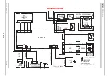
Page 22: ...J4 PB PB M MOTOR WITH PROTECTOR ORANGE BROWN CAPAC ITOR J3 1 2 3 BLACK RED BLUE J9 USER INTERFACE PCB NTC HEATER COVER ASSEMBLY DOOR SWITCH MAINS CONNECTION WITH SUPPRESSION L N E J10 4 3 2 1 BROWN J11 1 4 8 2 SENSING STRIP DRUM ASSY BLACK F FLAG RECEPTACLE PB PIGGY BACK M MALE TAB INSULATOR LOCKING RECEPTACLE CYCLING T STAT WHITE BLUE BLUE BLUE BLUE 5407404wd pdf TVF651 ALE600VX 16002194001 ...

Page 23: ...23 of 24 Indesit Company Service Manual UK English ...

Page 24: ...24 of 24 Service Manual UK Indesit Company English ...

Reviews: