background image

[b] FM-300AFE-HC, FM-300AFE-HCN 


Summary of Contents for FM-300AFE-HC

Page 1: ...NO F048 796 ISSUED MAR 1 2010 REVISED MAY 14 2010 SERVICE MANUAL HOSHIZAKI MODULAR ICE MAKER MODEL FM 481AGE HC FM 481AGE HCN FM 300AFE HC FM 300AFE HCN ...

Page 2: ...ant circuit unless qualified competent and authorised to do so If any component of the refrigeration circuit requires removal or replacement please contact the manufacturer HOSHIZAKI EUROPE LIMITED Telford 70 Stafford Park 7 Telford Shropshire TF3 3BQ UK Tel 44 0 1952 291777 Fax 44 0 1952 292777 ...

Page 3: ...M 300AFE HC FM 300AFE HCN 11 II MAINTENANCE AND CLEANING INSTRUCTIONS 12 1 EXTRUDING HEAD HOUSING BEARING AUGER BEARING 12 2 MECHANICAL SEAL 12 3 GEAR MOTOR 13 4 CONDENSER 13 5 AIR FILTER 13 6 WATER VALVE 14 7 CLEANING OF WATER SYSTEM 15 8 PERIODICAL CLEANING 17 III TECHNICAL INFORMATION 18 1 WATER CIRCUIT AND REFRIGERANT CIRCUIT 18 a FM 481AGE HC FM 481AGE HCN 18 b FM 300AFE HC FM 300AFE HCN 19 2...

Page 4: ...i THERMOSTATIC EXPANSION VALVE 29 6 ELECTRIC CIRCUIT 30 a BASIC OPERATION 30 b TIMING CHART 30 c SEQUENCE 33 d OPERATION BOARD 45 e CONTROLLER BOARD 45 f SURGE ABSORBER 46 g CAPACITOR XY FILTER 46 h BIN CONTROL SWITCH 46 i CHUTE SWITCH 47 j DEICING HEATER BELT HEATER 47 7 OPERATION BOARD 48 a USER OPERATION 48 b SERVICE OPERATION 48 8 PROTECTORS 52 a INDICATION 52 b PROTECTORS 52 9 ERROR CODES 55 ...

Page 5: ...refrigeration circuit This will temporarily reduce the ice production to avoid the overload condition c OVERLOAD ERROR When the above protection fails to evade the overload condition and the Gear Motor has a high current and a low rotation speed the icemaker will shut down for protection The icemaking mechanism will have extensive damage if this condition is repeated ten times In this case the ice...

Page 6: ...ke ice and nugget ice were available by replacing the Extruding Head and Cutter With the new models not only the Extruding Head and Cutter but also the refrigeration circuit is different between the flake ice model and nugget ice model To ensure the proper capacity and prevent a trouble with excessive ice production do not replace the Extruding Head and Cutter to change the ice type ...

Page 7: ...3 2 DIMENSIONS CONNECTIONS a FM 481AGE HC FM 481AGE HCN ...

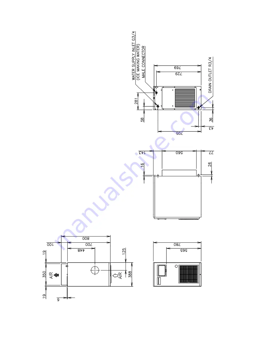
Page 8: ...4 b FM 300AFE HC FM 300AFE HCN ...

Page 9: ...5 3 SPECIFICATIONS a FM 481AGE HC ...

Page 10: ...6 b FM 481AGE HCN ...

Page 11: ...7 c FM 300AFE HC ...

Page 12: ...8 d FM 300AFE HCN ...

Page 13: ...0AFE HCN include Water Supply Evaporator Compressor Condenser and Control Assemblies As the unit is not equipped with an Ice Storage Bin this must be purchased separately as optional extra a FM 481AGE HC FM 481AGE HCN Control Box Compressor Reservoir Gear Motor Evaporator Flush Water Valve ...

Page 14: ...10 Drier Ice Chute Pressure Switch ...

Page 15: ...11 b FM 300AFE HC FM 300AFE HCN Control Box Compressor Reservoir Drier Ice Chute Gear Motor Pressure Switch Evaporator Flush Water Valve ...

Page 16: ...itions but normally the Bearings should be checked for wear after a total of 8 000 10 000 hour operation from installation date Note The clearance between the Auger blades and the Evaporator interior is 0 4 0 5 mm If the Bearings and rotating parts are worn out to create a larger clearance the Evaporator interior may be damaged The diameters differ by 0 8 1 0 mm If the Auger surfaces against which...

Page 17: ...Condenser once a year and clean if required by using a brush or vacuum cleaner More frequent cleaning may be required depending on the location of the icemaker 5 AIR FILTER Plastic mesh Air Filters remove dirt or dust from the air and keep the Condenser from getting clogged If the Filters get clogged the icemaker s performance will be reduced Remove and clean the Air Filters at least twice per mon...

Page 18: ...pply tap 3 Disconnect the Inlet Hose from the Water Valve 4 Remove the Mesh Filter from the Water Valve 5 Clean the Mesh using a brush 6 Replace the Mesh and Inlet Hose in their correct positions 7 Open the water supply tap 8 Connect the power source 9 Check for leaks ...

Page 19: ... to shorten cleaning time 6 Wipe off any splashed or spilt cleaner sanitiser immediately 7 Do not use any ammonia type cleaners on any part of the icemaker STEP 1 Dilute the solutions with water as follows Cleaning solution Nickel Safe Ice Machine Cleaner by The Rectorseal Corporation or similar Prepare approximately 3 L of solution as directed on the container Sanitising solution 30 mL of 5 25 so...

Page 20: ...further 20 minutes Open the Access Flap and press the Stop Button 12 Allow time for the Gear Motor to stop and the water system to drain 13 Unplug the icemaker 14 Refit the Top and Front Panels Plug in the icemaker 15 Allow the icemaker to make ice for approximately 10 minutes 16 Pour warm water into the Storage Bin to melt any ice down the drain Note 1 If the machine has heavy deposits of scale r...

Page 21: ...e thoroughly with a clean cloth and fresh water 3 Mix 5 litres of water with 18 mL of 5 25 sodium hypochlorite solution in a suitable container or the recommended Hoshizaki sanitiser as directed 4 Soak a clean sponge or cloth with the solution and wipe all the surfaces of the Bin Liner Ice Deflector and Door inner surface 5 Rinse thoroughly with fresh water and a clean cloth to wipe off the soluti...

Page 22: ...18 III TECHNICAL INFORMATION 1 WATER CIRCUIT AND REFRIGERANT CIRCUIT a FM 481AGE HC FM 481AGE HCN Pressure Switch Cut out 22 6 1 5 0 bar Cut in 15 7 1 5 bar ...

Page 23: ...19 b FM 300AFE HC FM 300AFE HCN Pressure Switch Cut out 22 6 1 5 0 bar Cut in 15 7 1 5 bar ...

Page 24: ...20 2 WIRING DIAGRAM a WIRING DIAGRAM FM 481AGE HC FM 481AGE HCN ...

Page 25: ...21 FM 300AFE HC FM 300AFE HCN ...

Page 26: ...22 b CONTROL BOX LAYOUT FM 481AGE HC FM 481AGE HCN ...

Page 27: ...23 FM 300AFE HC FM 300AFE HCN ...

Page 28: ... is located on top of the Evaporator The Deicing Heater Belt Heater around the top of the cylinder functions to reduce the load on the Gear Motor FM 481AGE HCN FM 300AFE HCN only See 5 REFRIGERATION CIRCUIT for further details b AUGER The stainless steel Auger is supported by the upper and lower Bearings of the Evaporator and slowly rotated by the Gear Motor while scraping off the ice forming on t...

Page 29: ...ector trips the Controller Board will stop the Gear Motor The Protector can be reset by the Reset Button on the Operation Board The Thermal Protector trips when the Gear Motor mechanism is overloaded or when excessively high or low voltage is applied on the Gear Motor The electrical capacity must be increased if a large current flows through the surrounding equipment h BELT HEATER FM 481AGE HCN FM...

Page 30: ...will automatically restart icemaking operation when the proper water level is resumed If the Float Switch trips at the upper float level on startup and trips at the lower float level request for water supply before the Compressor starts the icemaker will display E0 for a water leak error and shut down If the Float Switch trips at the upper float level and does not trip at the lower float level the...

Page 31: ...IONS In winter the water circuit must be completely drained out or otherwise protected to prevent freeze up and damage before shutting down the icemaker at night 1 Close the Water Supply Line Shut off Valve to stop water supply 2 Open the Air Shut off Valve 3 Press the Stop Button and drain the Float Tank and Evaporator Casing 4 Turn off the icemaker Before restarting the icemaker 1 Close the Air ...

Page 32: ...mal usage take utmost care when handling this icemaker so as not to cause any damages to the system In the case of accidental damage to the refrigeration system causing refrigerant leak do not create a source of ignition in the area Do not operate electrical switches or plugs in the area do not use naked flame Immediately ventilate the area by opening doors and or windows d COMPRESSOR The Compress...

Page 33: ...rovided for forced air cooling Use a vacuum cleaner or brush to remove dirt and dust between the spiral fins Be careful not to bend the fins g CONDENSER COOLING FAN MOTOR The Fan Motor cools the Air cooled Condenser and sends air to condense refrigerant gas inside the Condenser h DRIER The Drier uses desiccants molecular sieves activated alumina to absorb moisture in the refrigeration circuit The ...

Page 34: ...the Compressor starts to begin icemaking operation In normal operation the icemaker shuts down when the Storage Bin fills up to trip the Bin Control Switch or the Stop Button is pressed When the Compressor operates for 6 hours in total and continuously for more than 10 minutes the icemaker supplies water until the Reservoir fills up and starts a drain cycle After 10 minutes the icemaker automatica...

Page 35: ...31 FM 300AFE HC FM 300AFE HCN ...

Page 36: ...32 ...

Page 37: ...33 c SEQUENCE FM 481AGE HC FM 481AGE HCN 1 Startup Water Supply ...

Page 38: ...34 FM 481AGE HC FM 481AGE HCN 2 Startup After completion of water supply Gear Motor and Fan Motor start 5 min ...

Page 39: ...35 FM 481AGE HC FM 481AGE HCN 3 Startup Ice production starts ...

Page 40: ...36 FM 481AGE HC FM 481AGE HCN 4 Normal Operation Bin Control ...

Page 41: ...37 FM 481AGE HC FM 481AGE HCN 5 Shutdown Compressor stops 5 min ...

Page 42: ...38 FM 481AGE HC FM 481AGE HCN 6 Shutdown Drain ...

Page 43: ...39 FM 300AFE HC FM 300AFE HCN 1 Startup Water Supply ...

Page 44: ...40 FM 300AFE HC FM 300AFE HCN 2 Startup After completion of water supply Gear Motor and Fan Motor start 5 min ...

Page 45: ...41 FM 300AFE HC FM 300AFE HCN 3 Startup Ice production starts ...

Page 46: ...42 FM 300AFE HC FM 300AFE HCN 4 Normal Operation Bin Control ...

Page 47: ...43 FM 300AFE HC FM 300AFE HCN 5 Shutdown Compressor stops 5 min ...

Page 48: ...44 FM 300AFE HC FM 300AFE HCN 6 Shutdown Drain ...

Page 49: ...wn with a trouble an error code will be displayed immediately to notify the user To facilitate servicing ask the user for the applicable error code and prepare for the trouble in advance 4 Flush Timer The previous models were equipped with a Flush Timer that periodically flushes the water circuit to prevent water deposits from entering the Bearing and accelerating its wear The latest models have t...

Page 50: ...or at the same time When ice is used the Actuator will return to the original position to switch on the Proximity Switch The Gear Motor will restart in 7 seconds and the Compressor in 5 minutes When the Bin Control Switch seems to have malfunctioned check the dimensions of the Actuator as well as the operation of the Proximity Switch Also if the Chute Switch or the Gear Motor Circuit Protector has...

Page 51: ... Normal Condition Abnormal Condition Band moves and presses microswitch j DEICING HEATER BELT HEATER FM 481AGE HCN FM 300AFE HCN ONLY The Deicing Heater is provided to reduce the load of ice passing the Extruding Head and prevent vapor lock If the Extruding Head is clogged with ice a creaking sound will be heard or the Evaporator Cylinder will expand to break the soldered joint between the Cylinde...

Page 52: ...wer supply for the icemaker Turn it OFF to shut down the unit for a long time b SERVICE OPERATION Remove the Front Panel for access to the Option and Set Buttons CAUTION Removal of the Front Panel will expose moving and hot parts It is allowed for qualified service personnel only 1 Setting Model No The Model Setting No must be set to 34 at the time of replacement of the Controller Board Improper s...

Page 53: ...ess than 1 000 hours but less than 2 000 hours 25 indicates not less than 25 000 hours but less than 26 000 hours 4 Resetting Compressor Operating Hours Do not use this command unless necessary With the Operation Switch in the OFF position keep pressing the Ice Stop Option Buttons together and turn ON the Operation Switch Release the Buttons when the Display Window shows the ICE mode The Compresso...

Page 54: ...g the Option Button in the ICE or STOP mode The Display Window will show the compressor operating hours b 3 Press and release the Stop Button to display the error record b 5 The most recent errors will be displayed in reverse order of occurrence When appears press and release the Stop Button b 6 Press and release the Stop Button to indicate numerals and or letters six times When appears release th...

Page 55: ...es Release the Option Button to return to the original mode The freeze cycle time is displayed with two digits each for minutes o E 0 9 and seconds 0 5 0 9 Minutes o 0 9 0 9 min A 0 9 10 19 min b 0 9 20 29 min C 0 9 30 39 min d 0 9 40 49 min E 0 9 50 59 min Seconds 0 5 0 9 Example o 9 4 8 9 minutes 48 seconds b 7 3 6 27 minutes 36 seconds An approximate ice production capacity can be calculated fr...

Page 56: ... will stop When a service call is received ask the user to check which error code is in the Display Window Then see the error code table in 9 ERROR CODES to locate the cause b PROTECTORS 1 Compressor Internal Inherent Motor Protector Senses a temperature rise of the Compressor and internally shuts off the circuit Automatically resets when the temperature goes down If the Compressor takes a long ti...

Page 57: ...pout and Chute will be clogged with ice and disconnected to spill ice The Chute Switch is installed to prevent this trouble EL will appear in the Display Window when the Chute Switch operates 6 Low Water In case of low water or clogged water supply circuit the icemaker will shut down unless the Float Switch trips at the upper float level within 5 minutes after tripping at the lower float level The...

Page 58: ... condensing pressure when the icemaker has a clogged Air Filter or a dirty Condenser E4 will appear in the Display Window when the Pressure Switch trips five times within an hour 11 Voltage If the supply voltage is too low the Compressor may fail to start properly or the Gear Motor may lock to cause freeze up inside the Evaporator To prevent these troubles the icemaker will shut down and wait unti...

Page 59: ...Fan Motor Cooling water circuit Refrigeration circuit Condenser clogged Water supply Installation conditions E5 Gear Motor Drive Element Error Gear Motor is OFF on Controller Board while Rotation Sensor signals Gear Motor rotation or current flows Whole unit stops Press Reset Button Miswiring Gear Motor Magnet Switch or Relay Replace Controller Board E8 Discharge Pipe Temperature Error Discharge P...

Page 60: ...erly Memory circuit not available Replace Controller Board Error records and compressor operating hours not available on display c1 Low Water Water supply continues for more than 90 seconds or Float Switch trips at lower float level and does not reset for more than 60 seconds after water supply Whole unit stops until Reservoir fills up Only Control Water Valve operates intermittently for 5 minutes...

Page 61: ...Pressure bar Head Pressure1 bar Head Pressure2 bar Suction Pressure1 bar Suction Pressure2 bar 0 50 100 150 200 250 300 350 400 450 500 10 10 21 15 32 21 Ambient Temp Water Temp Ice Production Cspscity kg day Ice Production Capacity kg day 0 0 05 0 1 0 15 0 2 0 25 0 3 0 35 0 4 0 45 0 5 10 10 21 15 32 21 Ambient Temp Water Temp Water Consumption Water Consumption ...

Page 62: ...ressure bar Head Pressure1 bar Head Pressure2 bar Suction Pressure1 bar Suction Pressure2 bar 0 50 100 150 200 250 300 350 400 10 10 21 15 32 21 Ambient Temp Water Temp Ice Production Capacity kg day Ice Production Capacity kg day 0 0 05 0 1 0 15 0 2 0 25 0 3 0 35 0 4 10 10 21 15 32 21 Ambient Temp Water Temp Water Consumption Water Consumption ...

Page 63: ...ssure bar Head Pressure bar Suction Pressure bar 0 50 100 150 200 250 300 350 10 10 21 15 32 21 Ambient Temp Water Temp Ice Production Capacity kg day Ice Production Capacity kg day 0 00 0 05 0 10 0 15 0 20 0 25 0 30 0 35 10 10 21 15 32 21 Ambient Temp Water Temp Water Consumption m 3 day Water Consumption m 3 day c FM 300AFE HC ...

Page 64: ...ssure bar Head Pressure bar Suction Pressure bar 0 50 100 150 200 250 300 350 10 10 21 15 32 21 Ambient Temp Water Temp Ice Production Capacity kg day Ice Production Capacity kg day 0 00 0 05 0 10 0 15 0 20 0 25 0 30 0 35 10 10 21 15 32 21 Ambient Temp Water Temp Water Consumption m 3 day Water Consumption m 3 day d FM 300AFE HCN ...

Page 65: ...1 Coil winding opened 1 Replace f Water Valve 1 Coil winding opened 1 Replace 1 Closed 1 Open g Water Supply Tap 2 Water failure 2 Wait till water is supplied 1 Disconnected 1 Connect h Plug and Receptacle Control Box 2 Terminal out of Plug or Receptacle 2 Insert Terminal back in position i Chute Switch 1 Tripped 1 See III 6 i CHUTE SWITCH j Overload Protector 1 Tripped 2 Reset 1 The icemaker will...

Page 66: ... Bad contacts 8 Check for continuity and replace 3 Water has been supplied but the icemaker will not start d Pressure Switch 9 Loose connections 9 Tighten 1 Bad contacts 1 Check for continuity and replace Controller Board a X1 and X2 Relays 2 Coil winding opened 2 Replace Controller Board 1 Loose connections 1 Tighten 2 Motor winding opened or earthed 2 Replace b Compressor 3 Motor Protector tripp...

Page 67: ... PROBLEM POSSIBLE CAUSE REMEDY 1 Bearing worn out 1 Replace 2 Fan blade deformed 2 Replace fan blade a Fan Motor Condenser Unit 3 Fan blade does not move freely 3 Replace 1 Bearings worn out or cylinder valve broken 1 Replace b Compressor 2 Mounting pad out of position 2 Reinstall c Refrigerant Lines 1 Rub or touch lines or other surfaces 1 Replace d Gear Motor Ice Making 1 Bearing or Gear wear da...

Page 68: ...se 1 Clean or replace 2 Overflow from Reservoir Water does not stop c Float Switch 1 Bad contacts 1 Check for continuity and replace a Power Supply Voltage 1 Too high or too low 1 Connect the unit to a power supply of proper voltage 3 Gear Motor Protector operates frequently b Evaporator Assy 1 Bearings or Auger worn out 1 Replace Bearing or Auger ...

Page 69: ...eak into the refrigerant circuit unless qualified competent and authorised to do so If any component of the refrigeration circuit requires removal or replacement please contact the manufacturer HOSHIZAKI EUROPE LIMITED Telford 70 Stafford Park 7 Telford Shropshire TF3 3BQ UK Tel 44 0 1952 291777 Fax 44 0 1952 292777 ...

Reviews: