


Prerequisites:
•
The distance for the calibration must cor-
respond to the later drilling conditions (no
meadow, no pools of water and the like).
•
A distance of 100 m must be measured and
marked accordingly.
•
The vehicle with the connected machine is
ready for 100 m travel and is positioned at
the start of the marked section.
•
A wheel sensor is connected to the terminal.
•
The value “wheel sensor” was selected in the
“speed” parameter.
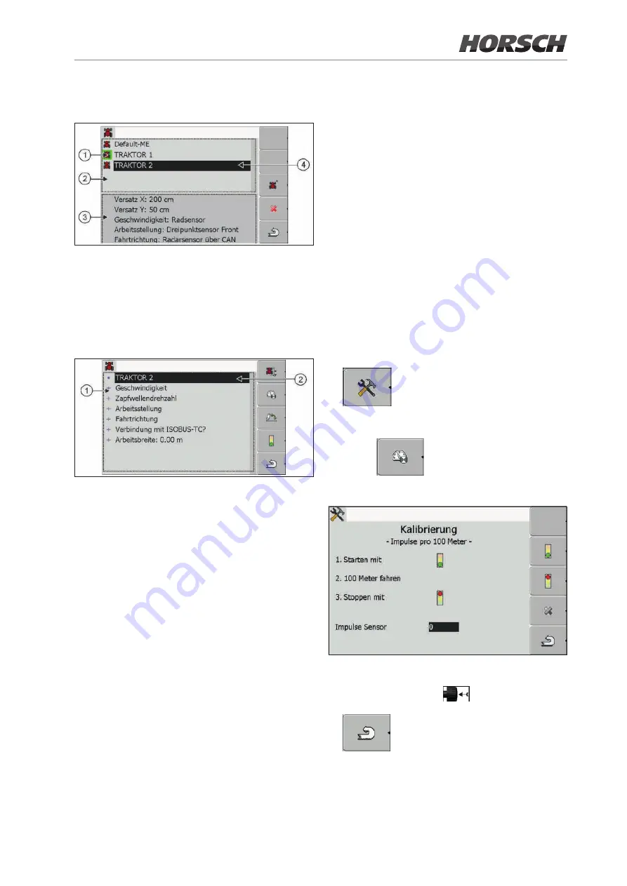
Procedure:
1. Call up the Tractor-ECU application.
2.
Open the vehicle list.
3.
Choose a vehicle profile.
4. Press
.
5. This screen appears:
6. To determine the 100 m method: Follow the
sequence of actions on the terminal or enter
the value manually
.
7.
Return to the vehicle profile. Cali
-
bration is completed.
¾
Call the vehicle list and select the activated
vehicle profile (green).
1
Activated vehicle profile (marked green)
2
List of all available vehicle profiles
3
Information about the marked vehicle
4
Cursor
¾
Configure the sensor speed, PTO shaft speed
and working position.
1
List of parameters
2
Cursor
Speed
Possible values for configuration:
•
“deactivated”: No sensor measures the speed.
•
“Wheel sensor”: A wheel sensor is connected
to the terminal and must be calibrated.
¾
Calibrate speed sensor (see Müller Elektronik
operating instructions, p. 57):
When using the 100 m method to calibrate the
speed sensor, the number of pulses the speed
sensor receives over a distance of 100 m is
determined.
If the number of pulses for the speed sensor is
known, they can also be entered manually.
72
73


