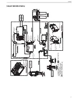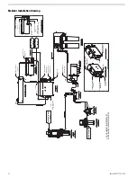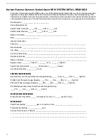
to Inlet of:
from Outlet of:
Step
Freshwater Flush Pressure Pump
**Unpressurized Potable Water Tank Line
8.
Freshwater Flush Check Valve
Freshwater Flush Carbon Filter
9.
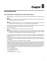
2. Connect Brine Discharge Line with the supplied 20 feet (6 meters) of 3/8” (9.5 mm) O.D. Brine Discharge Tubing:
to Inlet of:
from Outlet of:
Step
***Discharge Rinse Clean Valve
(center port)
ETD
located inside the system frame
1.
**Rinse Clean bucket or container
***Discharge Rinse Clean Valve
(left or right port)
2.
Brine Discharge Connector
***Discharge Rinse Clean Valve
(left or right port)
3.
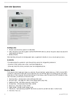
3. Connect Product Water Line with the supplied 30 feet (9.14 meters) of 3/8” (9.52 mm) O.D. nylon tubing:
to Inlet of:
from Outlet of:
Step
Brine Discharge Tee
Product Water Manifold Port "B" Unpotable
located inside the system frame
1.
Charcoal Filter
Product Water Manifold Port "A" Potable
located inside the system frame
2.
***pH Neutralizing Filter
Charcoal Filter
4.
***UV Sterilizer
***pH Neutralizing Filter
5.
**Potable Water Storage Tank Connector
***UV Sterilizer
5.
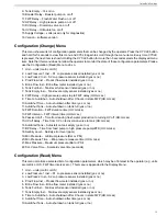
4. Connect Pressure pick-up with Pressure Gauges with the supplied 20 feet (6 meters) of 1/4” (6.35 mm) O.D.
nylon tubing:
to Inlet of:
from Outlet of:
Step
Inlet Compound Vacuum/Pressure Gauge
located inside the system frame
Booster Pump Pressure Pick Up Tee
located on booster pump
1.
Ultraviolet (UV) Light Installation
The SP-Series UV unit is shipped with the UV lamp, quartz sleeve, fittings and O-rings and needs to be assembled
before the UV unit can be used.
1. Install the UV unit in a sheltered, well-ventilated area.
2. Install the UV unit as close as possible to the point-of-use to avoid potential contamination discharge from pipes,
fittings, etc.
3. The UV unit should be mounted on stable support to avoid straining or warping. Allow sufficient clearance
around the unit for servicing.
4. Verify the location is free from vibration.
5. All UV units are rated for maximum operating pressure at 50psig (8.24 bar).
6. The UV unit must be properly grounded for safe and proper operation. Failure to properly ground the UV unit
automatically voids all unit warranty.
7. Line voltage must be within 10.56V to 16.50V. Voltage outside the range will compromise the performance of
the UV unit.
Seafari QUEST 200-600
28
Summary of Contents for Seafari Quest Compact 200
Page 2: ......
Page 3: ...Seafari QUEST 200 600 Owner s Manual Horizon Reverse Osmosis Manual PN B651100001...
Page 4: ......
Page 8: ......
Page 16: ......
Page 22: ......
Page 52: ......
Page 60: ......
Page 62: ...2 12 4 12 8 10 7 3 1 6 5 9 12 11 4 Seafari QUEST 200 600 60...
Page 68: ...11 13 6 14 16 1 4 5 9 3 10 8 2 7 8 15 12 Seafari QUEST 200 600 66...
Page 70: ...9 3 5 4 1 10 8 16 14 11 2 15 12 13 7 8 6 Seafari QUEST 200 600 68...
Page 72: ...11 13 6 14 16 1 4 5 9 3 10 8 2 7 8 15 12 Seafari QUEST 200 600 70...
Page 74: ...9 3 5 4 1 10 8 16 14 11 2 15 12 13 7 8 6 Seafari QUEST 200 600 72...
Page 76: ...13 15 8 16 9 1 6 7 4 12 11 3 10 11 20 14 5 2 21 19 17 18 Seafari QUEST 200 600 74...
Page 78: ...4 7 6 1 12 11 9 16 13 3 20 14 15 10 11 8 5 2 18 21 19 17 21 Seafari QUEST 200 600 76...
Page 80: ...13 15 8 16 9 1 6 7 4 12 11 3 10 11 20 14 5 2 21 19 17 18 Seafari QUEST 200 600 78...
Page 82: ...4 7 6 1 12 11 9 16 13 3 20 14 15 10 11 8 5 2 18 21 19 17 21 Seafari QUEST 200 600 80...
Page 85: ...9 9 6 3 8 7 1 5 1 4 9 6 2 11 12 10 12 10 1 83 Exploded Parts View...
Page 89: ...19 10 13 20 4 15 5 3 8 6 14 15 11 9 7 13 10 20 2 19 18 22 21 12 16 17 1 87 Exploded Parts View...
Page 91: ...5 6 2 3 2 6 7 9 9 8 1 10 5 89 Exploded Parts View...
Page 101: ...12 8 9 2 10 13 1 3 5 4 14 11 6 15 7 99 Exploded Parts View...
Page 104: ...8 15 14 13 6 2 1 16 5 10 3 6 6 8 4 12 7 15 11 9 Seafari QUEST 200 600 102...
Page 114: ......
Page 115: ......


