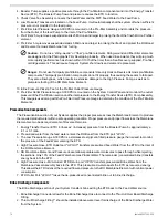
Install Lamp
Perform this procedure only after the quartz sleeve installation and leak-tests are completed successfully
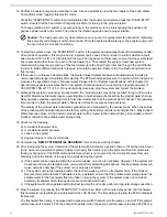
1. Connect the UV lamp to the 4-point receptacle. If the lamp is not installed properly, lamp breakage will occur.
2. Insert lamp into quartz sleeve through compression nut pass-thru.
3. Install rubber boot over compression nut.
4. Connect unit power cable to power source.
5. Tighten the 4 screws to secure ballast box cover.
6. Turn ON the power to the unit.
7. Verify UV lamp operation from the viewport.
8. Allow one minute for the UV lamp to warm up prior to flowing water through the UV unit.
Caution:
Use the viewport to verify the proper operation of the UV lamp.
Caution:
Rapid successive cycling of the power to the ballast can cause premature failure of the unit.
Caution:
Prior to energizing the lamp, make sure there is no water leaking from the quartz sleeve
compression nuts.
Mounting the Unit
Once the UV unit is assembled and tested successfully, it can be mounted onto its permanent operational location.
The unit must be mounted in a manner that will prevent excessive vibration and warping which will damage the
quartz sleeve.
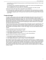
Operational Notes
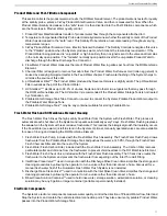
• Release the pressure in the UV treatment chamber before breaking the compression nut seals.
• Disconnect all power to the UV unit before servicing.
• Do not allow the inlet water temperature to drop below 35ºF (2ºC).
• Do not allow the flow rate to exceed 2 GPM.
• Do not cycle the UV unit more than 3 "ON/OFF" cycles in a 24-hour period.
• Ensure all plumbing connections are tightly sealed before applying pressure.
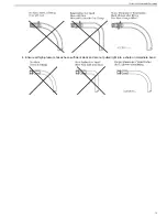
• Before connecting the return tube, flush the unit to rinse out any debris left from the installation process.
Danger:
UV LIGHT EXPOSURE CAN SEVERELY BURN AND DAMAGE EYES AND SKIN.
Danger:
DO NOT look at the blue UV light. DO NOT operate the UV lamp outside of the UV treatment
chamber.
Danger:
The unit operates on high voltage and must be serviced by qualified personnel only.
Caution:
Standard flow rate are based on water temperature 35ºF to 100ºF. If the inlet water temperature
exceeds 100ºF (38ºC), please contact your local CSR.
Caution:
Cycling more than 3 cycles will reduce the end-of-life (EOL) output and/or cause premature lamp
failure.
Seafari QUEST 200-600
30
Summary of Contents for Seafari Quest Compact 200
Page 2: ......
Page 3: ...Seafari QUEST 200 600 Owner s Manual Horizon Reverse Osmosis Manual PN B651100001...
Page 4: ......
Page 8: ......
Page 16: ......
Page 22: ......
Page 52: ......
Page 60: ......
Page 62: ...2 12 4 12 8 10 7 3 1 6 5 9 12 11 4 Seafari QUEST 200 600 60...
Page 68: ...11 13 6 14 16 1 4 5 9 3 10 8 2 7 8 15 12 Seafari QUEST 200 600 66...
Page 70: ...9 3 5 4 1 10 8 16 14 11 2 15 12 13 7 8 6 Seafari QUEST 200 600 68...
Page 72: ...11 13 6 14 16 1 4 5 9 3 10 8 2 7 8 15 12 Seafari QUEST 200 600 70...
Page 74: ...9 3 5 4 1 10 8 16 14 11 2 15 12 13 7 8 6 Seafari QUEST 200 600 72...
Page 76: ...13 15 8 16 9 1 6 7 4 12 11 3 10 11 20 14 5 2 21 19 17 18 Seafari QUEST 200 600 74...
Page 78: ...4 7 6 1 12 11 9 16 13 3 20 14 15 10 11 8 5 2 18 21 19 17 21 Seafari QUEST 200 600 76...
Page 80: ...13 15 8 16 9 1 6 7 4 12 11 3 10 11 20 14 5 2 21 19 17 18 Seafari QUEST 200 600 78...
Page 82: ...4 7 6 1 12 11 9 16 13 3 20 14 15 10 11 8 5 2 18 21 19 17 21 Seafari QUEST 200 600 80...
Page 85: ...9 9 6 3 8 7 1 5 1 4 9 6 2 11 12 10 12 10 1 83 Exploded Parts View...
Page 89: ...19 10 13 20 4 15 5 3 8 6 14 15 11 9 7 13 10 20 2 19 18 22 21 12 16 17 1 87 Exploded Parts View...
Page 91: ...5 6 2 3 2 6 7 9 9 8 1 10 5 89 Exploded Parts View...
Page 101: ...12 8 9 2 10 13 1 3 5 4 14 11 6 15 7 99 Exploded Parts View...
Page 104: ...8 15 14 13 6 2 1 16 5 10 3 6 6 8 4 12 7 15 11 9 Seafari QUEST 200 600 102...
Page 114: ......
Page 115: ......

