Honeywell WV8840A Installation Instructions Manual Download Page 7

WV8840A WATER HEATER CONTROLS

7

69-2247—05

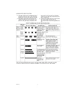
Troubleshooting Without Status Indicator Assistance

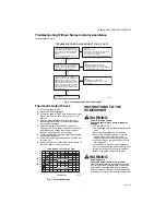
Follow diagram in Fig. 6.

Fig. 6. Troubleshooting without status light.

Thermopile Output Check

1.

Turn device knob to OFF.

2.

Disconnect thermopile leads.

3.

Turn device knob to PILOT, hold down knob to light 

pilot burner. Hold the knob down for five or more 

minutes.

4.

After five minutes, check thermopile output by 

connecting the voltmeter to the positive red lead 

and negative white lead.

5.

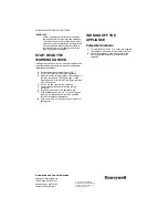
Output should be at least 350 mV. (See Fig. 7.

Connect the 3.6 ohm resistor between the two ther-

mopile leads, the voltage should be at or higher 

than one half of the open circuit voltage.

6.

The terminal housing prevents miswiring of positive 

and negative leadwires.

7.

Flame must envelop thermopile at Hot Junction (3/8 

in. below tip).

8.

Keep heat away from cold junction (brass sleeve of 

the thermopile) for maximum output.

Fig. 7. Thermopile output.

INSTRUCTIONS TO THE 

HOMEOWNER

WARNING

Fire or Explosion Hazard.

Can cause severe injury, death or property 

damage.

1. IF YOU SMELL GAS:

•Turn off the gas supply at the appliance service 

valve.

•Do not light any appliances in the house.

•Do not touch electrical switches or use the 

phone. Leave the building and use a 

neighbor’s phone to call your gas supplier.

•If you cannot reach your gas supplier, call the 

fire department.

2. The water heater control must be replaced in 

event of any physical damage, tampering, bent 

terminals, missing or broken parts, stripped 

threads or evidence of exposure to heat.

WARNING

Scalding Hazard.

Can cause burns, severe injury or death.

Never move temperature setpoint knob past the 

HOT setting without checking water temperature 

at the faucet, and readjusting until comfortably 

warm to the touch. Consider the ages and health 

of all who will come into contact with heated water.

TURN DEVICE KNOB FROM OFF TO 

PILOT, PRESS DOWN KNOB AND HOLD, 

LIGHT PILOT BY DEPRESSING PIEZO 

IGNITION BUTTON, PILOT SHOULD 

LIGHT.

–  WATER TEMPERATURE IS BELOW 

  THE CUT-OUT LIMIT

CHECK:

• WIRING OF THERMOPILE LEADS

• FLAME COVERAGE OF THERMOPILE

   – THERMOPILE OUTPUT IS TOO LOW-RUN 

     THERMOPILE OUTPUT CHECK

STATUS LIGHT SHOULD FLASH AFTER  

1 MINUTE, LED WILL FLASH NORMAL  

SINGLE BLINK, RELEASE THE DEVICE  

KNOB, PILOT SHOULD REMAIN LIT 

TURN DEVICE KNOB TO DESIRED

TEMPERATURE SETTING, BURNER WILL

TURN ON ONLY IN ACTIVE CALL FOR

HEAT (WATER TEMPERATURE IS LESS 

THAN TEMPERATURE SETTING MINUS 

DIFFERENTIAL); LED FLASHES 1 TIME 

EVERY 3 SECONDS WHILE IDLE AND 

STROBES EVERY 3 SECONDS DURING 

A CALL FOR HEAT.

SYSTEM OK

CHECK:

• EXCESSIVE INLET PRESSURE

• TANK TEMPERATURE IS AT OR CLOSE

  TO SET POINT

NO 

NO 

NO 

YES

YES 

YES

M29431

TROUBLESHOOTING GUIDE WITHOUT STATUS LIGHT 

CHECK:

• INLET PRESSURE

• MAKE SURE AIR IS BLED OUT OF SYSTEM

• PIEZO SPARKING TO THERMOPILE

• CLOGGED PILOT ORIFICE

• GAS LEAK IN PILOT TUBING CONNECTIONS

M22535B

TIME (MINUTES)

OUTPUT (mV)

THERMOPILE OUTPUT WITH TIME

500

600

400
300
200
100

0

0

1

2

3

4

5

6

7

8

9

10

900
800
700

NORMAL RANGE

OUTPUT TOO LOW

Summary of Contents for WV8840A

Page 1: ... is shown on the product label Inlet Pressure Range See appliance rating plate for inlet pressure range recommendation 1 2 PSI 14 0 in w c maximum inlet pressure allowed for proper operation Body Pattern 90 degrees with 1 2 in inlet and 1 2 in inverted flare outlet Mounting Mounting in upright position only Control Input Voltage Minimum 350 mV dc open circuit Voltage Maximum 850 mV dc open circuit...

Page 2: ...l or agricultural applications protect the control with a cover Dust or Grease Accumulation Heavy accumulations of dust or grease can cause the control to malfunction Where dust or grease can be a problem provide covers for the control to limit contamination Heat Excessively high temperature can damage the control Make sure the maximum ambient temperature at the control does not exceed the rating ...

Page 3: ...1 Use a new properly reamed pipe free from chips If tubing is used make sure the ends are square deburred and clean All tubing bends must be smooth and without deformation 2 Ensure that gas supply is turned off 3 Run pipe or tubing to the water heater control If tubing is used obtain a tube to pipe coupling to connect the tubing to the control 4 Install a sediment trap in the supply line to the wa...

Page 4: ...t of 1 2 in pipe with 5 in w c pressure 2 Depress the piezo igniter to light the pilot flame and hold the knob in until the status indicator starts to blink approximately 30 seconds indicating pilot now being held by electronics NOTE LED should blink once every three seconds If not check the error codes in Table 3 3 Release the knob and turn to the desired temperature setting The burner will come ...

Page 5: ...ow rate 1 Check the full rate manifold pressure listed on the appliance nameplate Water heater control full rate outlet pressure should match this rating 2 With burner operating check the water heater control flow rate using the meter clocking method or check pressure using a manometer connected to the outlet pressure tap on the water heater control See Fig 5 MAINTENANCE WARNING Fire or Explosion ...

Page 6: ...ronics is holding the Pilot Valve open and the Main Valve closed You can now turn the knob to a desired setpoint temperature LED will continue to flash 1 time every 3 seconds while in Idle mode no call for heat Strobe every 3 seconds Not an error indicates call for heat during normal operation Main valve open None Action required 2 flashes Low thermopile voltage main valve not turned ON Check ther...

Page 7: ...ed in event of any physical damage tampering bent terminals missing or broken parts stripped threads or evidence of exposure to heat WARNING Scalding Hazard Can cause burns severe injury or death Never move temperature setpoint knob past the HOT setting without checking water temperature at the faucet and readjusting until comfortably warm to the touch Consider the ages and health of all who will ...

Page 8: ...bove the previous temperature follow these instructions 1 Set the temperature setpoint knob to OFF 2 Turn off the main gas valve to the appliance 3 Wait five minutes to clear out any unburned gas If you then smell gas STOP Follow step 1 in the warning above If you DO NOT smell gas continue with the next step 4 Turn on the gas supply to the appliance 5 Restart the appliance by performing lighting p...

Reviews: