background image

l1/Z”   A P P R X   (13mm)

MOTOR
PULLEY

1938

Fig. 2.

BELT ADJUSTMENT

Hand pressure should depress the belt about  1/2 inch.

See Figure 2. The belt should be tight enough so that no
slipping occurs. A belt that is unnecessarily tight can
cause excessive wear.

Adjust belt tension by loosening the motor  hold-

down bolts, moving the motor until tension is correct.

Then retighten the bolts. Make certain that belts and
pulleys are aligned properly. If a belt becomes worn or
frayed, replace it.

PRESSURES

When making weekly maintenance checks, verify that

the tank pressure is in the 70 to 90 psi (480 to 620 kPa)
range. Also make certain that the PRV pressure for

each 

unit is at the proper setting.

COMPRESSOR OPERATION

As part of the weekly operational check, confirm that

the compressor does 

have 

an “off" period and is not

running continuously. Note that on WP240 Compressors,

the manual alternation system should be switched over
to confirm the start-up and off cycle of both pumps.

Every three months, the cut-in pressure, pump up

time, cut-out pressure, and off time should be measured
under normal operating conditions. It should be below
50 percent operation, that is, it should have more off
time than on time. It should operate approximately
from 70 to 90 psi (480 to 620  kPa)  on the  1/4 to  5 HP
units and from 60 to 100 psi (415 to 690 kPa) on the
7-l/2 to 20 HP units. Note that on the WP240 units, 

the

pumps should be switched and rechecked (switching is
automatic on some units).

A good maintenance practice is to keep 

these 

figures

for practice. If possible, attach a card with the figures to
the device. Decreasing off periods with no change in the
pressure range indicate an increase in air consumption,
Pump up times will increase also. This can be caused by
added devices or leaks. Increasing pump up time with 

no

change in the pressure range or off time indicates wear in

the compressor and may warrant closer observation, This

is usually followed by an increase in oil consumption.

If there is suspicion of wear, the dead ended pump

up time (pumping up the tank with the system shut off)

should be checked against the value given in the data

table. If it differs from the data table by more than 10
percent, then an analysis of the cause should be made
and the situation corrected. Refer to the  WP240  Wiring
Diagrams and the WP250  Wiring Diagrams for operation
unique to these models.

TROUBLESHOOTING

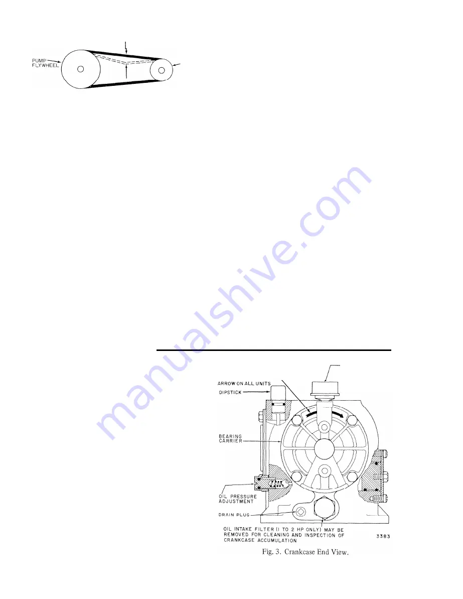
ROTATION OF FLYWHEEL
MUST BE IN THE SAME
DIRECTION AS THE

\

OIL

PRESSURE

GAGE

WRONG  OIL  PRESSURE

Normal oil pressure for these compressors is from 10

to 20 psi (70 to 140 kPa). There should be no pressure
during the “Off”  cycle. Check the oil level and clean the
oil intake filter before adjusting pressure. The oil pres-
sure is regulated by a spring loaded ball that is mounted
in the bearing carrier or in the crankcase near the bearing
carrier. See Figure 3, This is on the same side as the dip-
stick. The spring pressure is controlled by an adjusting
screw. Turning the screw inward will increase the pres-
sure.

Be sure to loosen the adjustment lock nut before

making any adjustment. Turn the adjustment screw

slowly until the oil gauge registers approximately 1.5 psi

(105  kPa). After the adjustment has been made, tighten

the adjustment screw lock nut.

75-7131

Summary of Contents for WP230A-M

Page 1: ...Maintenance Schedule 2 Maintenance 2 Troubleshooting 4 Repair 7 Parts List 10 Ordering Information 14 WP240 Wiring Diagrams 14 WP250 Refrigeration Drier Operation Check 16 Data Tables 17 Rev 7 77 J R W Form Number 75 7131 Commercial Div ...

Page 2: ...essor is installed in an extremely dirty or dusty atmosphere the filters may need to be changed more frequently The three month checks will indicate a need for more frequent replacement uincy units of 1 4 to 3 4 are splash lubricated P units and larger are pressure lubricated A dipstick is provided on all units for checking the oil level To check the oil level stop the pump remove the dipstick wip...

Page 3: ...ned in a nonflammable solvent or warm soapy water The 1 4 to 2 HP compressors manufactured after September 1974 have one piece replaceable filters These should be visually checked for foreign material build up A dirty filter causes excessive oil consumption and should be replaced FILTER CARTRIDGE The condition of the filter element may be checked by noting the line pressure after the filter if a g...

Page 4: ...practice If possible attach a card with the figures to the device Decreasing off periods with no change in the pressure range indicate an increase in air consumption Pump up times will increase also This can be caused by added devices or leaks Increasing pump up time with no change in the pressure range or off time indicates wear in the compressor and may warrant closer observation This is usually...

Page 5: ...eak clean the unit thoroughly and sprinkle the areas suspected with baby powder Make certain not to get any baby powder into the intake Recheck the device after several hours and the leak should be more easy to locate Excessive oil on the after cooler pipe or compressor head usually indicates air leaks Locate these with a soap and water solution when the unit is operating The un loaders should als...

Page 6: ...art make certain power is applied and fuses installed With W240 units checkout of electrical power application to the pump motor will differ with the operation requirements of each system See wiring diagrams If a voltage tester is available check for proper power at the motor terminals If no power trace wiring back towards the source to locate the problem CHECK FIRST AT THE PRESSURE SWITCH If ther...

Page 7: ... beneath if necessary If the source of the trouble has still not been located remove and inspect intake and exhaust valves for dirt or warpage NOTE The head must be removed on the 1 2 HP unit to service valves as they are not removable The piston top and cylinder walls can be inspected at this time PUMP SLOWS STALLS OR GOES OUT ON OVER LOAD This is probably the result of the pump seizing Check oil...

Page 8: ...ing removal The oil pump is factory ground as an assembly and partial replacement is not possible In the event that the pump or crank bearing which is part of the pump is deemed faulty it should be replaced as a unit The assembly is held by four bolts see Fig 4 front view The replacement does not include an oil gauge If needed it must be ordered separately After reinstallation the oil pressure mus...

Page 9: ...D EXHAUST VALVES UNLOADER The intake valves exhaust valves and unloader mechanisms can be disassembled for inspection clean ing or repair in all sizes except the 1 2 HP The 1 2 HP unit is a sealed assembly in the head In the event the valves are deemed defective in this unit replace the head assembly Quincy Part No 2400 X2P On the 1 4 HP unit remove the two valve locking nuts in the head and the v...

Page 10: ...ro Corp filter and Norgren regulator and relief valve To perform any maintenance and repair work on the PRV station first shut off air supply from tank Then bleed down system by manually operating the drain push red button on drain valve Note that all valves and dampers will return to their normal position The regulator and relief valve can now be removed and replaced or repaired in place with the...

Page 11: ...Intake and Exhaust Valves 1 2 HP Unit UNLOADER h YiBkF EXCEPT I HP QUINCY PT 7 4 8 3 X INTAKE VALVE ASSY EXHAUST VALVE ASSY 1945 3 4 1 1 2 HP 3 4 1 1 2 H P QUINCY 4610X QUINCY 1919 X Fig 15 WP230 Unloader Assembly 3 4 HP Units and Up INTAKE VALVE ASSY EXHAUST VALVE ASSY 1979 3 4 AND I l 2 HP 3 4 AND l l 2 HP QUINCY PT 6540X QUINCY PT 8133 Fig 16 WP240 Unloader Assembly 1HP Fig 17 Mechanical Unload...

Page 12: ... 7483 X INTAKE ASSEMBLY DISCHARGE ASSEMBLY WP230 QUINCY PT 6671XU QUINCY PT 6670X Fig 19 WP230F G bly 2 and 3 HP Units Fig 20 WP230H M 5 to 20 and 3 HP Head Assembly 240F and G 2 Typical PTM Pall Trinity Micro Filter PRV Arrange ment 0n 3 HP and Larger Units Filter PRV Station For 1 4 to 2 HP well Stations See Form No 75 2558 BY CUSTOMER TOP VIEW WALL OUNTED FRONT VIEW Fig 21 all Mounted ELEMENT S...

Page 13: ...PRV Parts List Fig 22 e MCC1001SU160Y 6 1 Valve l f b6154 6155 I 4 9 1 Cage 160 psi 305917 00106 q5 10 Bracket Tank 8350 8351 8352 4 Notes 1 Order from PTM 2 Order from Norgren 3 Obtain Locally 4 Order from Quincy 5 Order from Honeywell 13 75 713 1 ...

Page 14: ...number WP240 WIRING DIAGRAMS The two most common ways the WP240 Air Com pressor can be used are 1 Manual selection of first stage pump unit with automatic second stage backup See Figures 10 and 11 Honeywell M O D E L WP250 Colt Industries Quincy Compressor Division Quincy Illinois u s A ERlAL DATE CODE 1 1 J 75 7131 d Fig 23 PTM Pall Trinity Micro Parts Local distributor or Pall Trinity Micro Corp...

Page 15: ... 13 L2 _ L2 4 Ll L 2 LI 4 _ i 3 Ml COMP I 5 3 2 1 S E T P S 2 5 10 P S I B E L O W P S 1 5323 Fig 26 Manual Alternation with Automatic Backup for Fig 28 Automatic Alternation with Backup and Isolated Three Phase Units Quincy Wiring Package No Control Quincy Wiring Package No 1485A WP1582 120 Volt Control Only Fig 27 Automatic Alternation with Automatic Backup for Single Phase Units Only 6 0 HZ ALT...

Page 16: ...ing the correct power supply see name plate Feel condensate discharge outlet ahead of trap and as close to drier as possible The outlet should be cool to the touch about 40 to 45 F under all operational con ditions no flow to full capacity flow of compressed air If drier has not been running energize drier and check for gradual decrease in temperature at condensate outlet Conduction of cold throug...

Page 17: ... 70 480 70 480 70 480 70 480 70 480 70 480 60 415 60 415 60 415 60 415 90 620 90 620 90 620 90 620 90 620 90 620 90 620 90 620 100 690 100 690 100 690 1 100 690 Inlet Size NPT Compr 1 4 6 l 2 13 3 4 19 l 2 13 3 4 19 l l 4 31 l 1 4 31 2 50 2 50 2 50 I Note Part Numbers listed are Quincy numbers aOrder Replacement Elements from Honeywell Local Business Office bO to 60 psi 0 to 415 kPa on 7 l 2 to 20...

Page 18: ...P240D WP24OE WP240F WP240G Quincy Model No FFHX2 FFHlO6 FFHlO8 FFH210 FFH216 FFH230 FFH240 a Each WP240 model has two identical motor pump units Data specified is applicable to both units b UnIoader solenoid in aftercooler line c Order Replacement Elements from Honeywell Local Branch Office ...

Page 19: ......

Page 20: ...innati OH 513 948 4185 Cleveland OH 216 361 7373 Dallas TX TEXAS Austin TX 512 478 1788 WYOMING Casper WY 307 265 9374 or 1 800 443 8446 Toll Free NEBRASKA Omaha NB 402 331 3200 Columbus OH 214 387 5416 614 486 5971 X210 El Paso TX 915 533 9924 NEW HAMPSHIRE Dayton OH Bedford NH 513 237 4035 603 625 6502 Ft Worth TX 214 263 2311 Toledo OH NEW JERSEY 419 473 972 X214 Mt Laurel N J 609 234 2224 Youn...

Reviews: