13 - 2
•
Clorox
®
Bleach – 10%
•
Gentle dish soap and water
Inspecting Cords and Connectors
Inspect the interface cable and connector for wear or other signs of dam-
age. A badly worn cable or damaged connector may interfere with scanner
operation. Contact your distributor for information about cable replace-
ment. Cable replacement instructions are on
Replacing Cables
The standard interface cable is attached to the scanner with an 15-pin modular
connector. The interface cable is designed to be field replaceable.
•
Order replacement cables from Honeywell or from an authorized distributor.
•
When ordering a replacement cable, specify the cable part number of the
original interface cable.
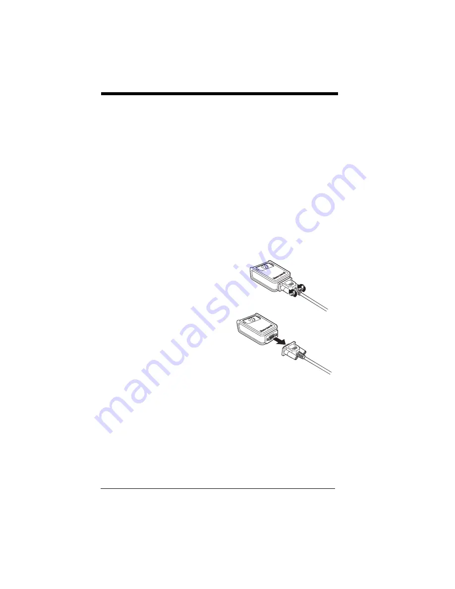
Replacing an Interface Cable
1. Turn the power to the host system
OFF.
2. Disconnect the scanner’s cable
from the terminal or computer.
3. Rotate the two screws counter
clockwise to loosen the screws.
4. Gently pull the connector.
5. Replace with the new cable.
Insert the connector into the
socket on the 3310. Rotate the
two screws clockwise to tighten.
Troubleshooting a
Corded Scanner
The scanner automatically performs self-tests whenever you turn it on. If
your scanner is not functioning properly, review the following Troubleshoot-
ing Guide to try to isolate the problem.
Is the power on? Is the aimer on?
If the aimer isn’t illuminated, check that:
•
The cable is connected properly.
•
The host system power is on (if external power isn’t used).
•
The button works.
Summary of Contents for Vuquest 3310g
Page 1: ... Vuquest 3310g Area Imaging Scanner User s Guide ...
Page 8: ......
Page 17: ...ix Unicode Key Maps A 13 ...
Page 18: ...x ...
Page 24: ...1 6 ...
Page 80: ...3 30 ...
Page 88: ...4 8 ...
Page 108: ...5 20 ...
Page 196: ...8 20 ...
Page 200: ...9 4 ...
Page 206: ...10 6 ...
Page 246: ...11 40 ...
Page 256: ...13 4 ...
Page 272: ...A 14 ...
Page 275: ...Sample Symbols Aztec MaxiCode Micro PDF417 Package Label Test Message Test Message ...


