


MeshGuard Network Deployment Guide
MeshGuard Zero Calibration
1. From Detection Mode, press and hold [MODE] and [N/-] to enter Programming Mode. When you see “Pro,” release the keys.
2. When “CAL” and “go” are displayed, and “ZERO” is shown, the MeshGuard is ready to perform a zero (fresh air) calibration.
3. Press [Y/+]. The LCD displays “go.” The display counts down from 10 to 0.
4. After the countdown reaches 0, the LCD displays “dn,” for “done.” The reading should show 0. Otherwise, repeat the zero calibration.
Setting MeshGuard Low Alarm, High Alarm, And Span Values
1. From Detection Mode, press and hold [MODE] and [N/-] to enter Programming Mode. When you see “Pro,” release the keys.
2. When “CAL” and “go” are displayed, press [N/-] until the display shows the High Alarm, Low Alarm, or Span Set screen.
3. Press [Y/+] to enter and change the setting. Press [MODE] to go back to Detection Mode or [N] to advance to the next menu.
4. The LCD displays the current value. Change the value if necessary.
To change the value:
1. Press [Y/+] to increase the number and [N/-] to decrease it.
2. Press [MODE] to advance to the next digit.
3. After moving to the last digit and making changes, press [MODE]. A question mark (?) is shown in the display, asking if you want to
save the change.
•
Press [Y/+] for yes. The message “dn” means the change is done.
•
Press [N/-] for no. A “no” message means that the change was abandoned.
•
Press [MODE] to return to the first digit.
MeshGuard Span Calibration
1. Attach a cylinder of calibration gas to the calibration adapter, and attach the calibration
adapter to the MeshGuard’s sensor.
2. From Detection Mode, press and hold [MODE] and [N/-] to enter Programming Mode.
When you see “Pro,” release the keys.
3. When “CAL” and “go” are displayed in alternation, press [N/-].
The display shows “CAL” and “go” in alternation, with the word “SPAN” shown along the
top. The MeshGuard is ready to perform a span calibration.
4. Press [Y/+]. The LCD displays “go.” Connect the calibration gas adapter to the Mesh-
Guard, and connect the gas cylinder to the adapter. Start the flow of gas.
5.
When the gas flow starts, the LCD displays “gAS” and the span concentration value.
6. After the countdown reaches 0, the LCD displays “dn,” for “done.” The reading should
equal the span gas’ concentration value. Otherwise, repeat the span calibration.
If the MeshGuard does not detect gas after counting down to 0, the LCD displays “Err” (for “error”). The LED glows red and the buzzer
sounds to provide extra warning. The MeshGuard automatically returns to the span calibration display.
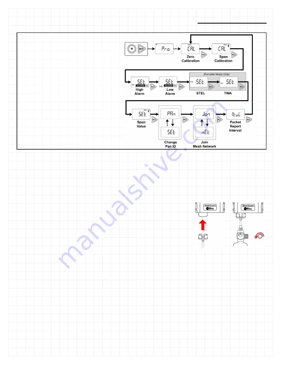
MeshGuard Programming
MeshGuard allows you to step through
programming screens and set parameters.
•
Enter Programming Mode by turning on
the MeshGuard and then holding down
[MODE] and [N/+] until “Pro” appears in
the display.
•
Step from one set of parameters to the
next by pressing [N/-].
•
Enter a submenu to make changes by
pressing [Y/+].
•
Exit to Detection Mode by pressing
[MODE].
Detailed descriptions of all programming
functions are covered in the MeshGuard User’s
Guide.
Note:
Portable Mode does not apply to MeshGuard LEL.


