60-2035—9
6
RA890G
OPERATION AND CHECKOUT
IMPORTANT: If limit control opens, ignition and fuel
valves are de-energized, but safety switch lockout will
not occur. When normal conditions are restored and
the limit closes, the RA890G recycles.
CHECKOUT REQUIRED
Before the installation is complete, satisfactorily com-
plete all checkout tests indicated below. Repeat these tests
after any adjustments are made to the system.
Flame Current Check (all installations).
Pilot Turndown Test (all installations that required proof
of pilot before main fuel valve is opened).
Ignition Spark Response Test (all installations).
Safe Shutdown Checks—Flame failure, power failure,
limit action (all installations).
FLAME CURRENT CHECK
The Flame Current Check is the best indicator of proper
flame detector application. Perform the check at the time of
installation, at any time service is done on the system, and at
least once a month (or more often) while the system is in
operation. This prevents shutdowns due to poor flame signal.
Use a W136A Microammeter, or equivalent, and read the
flame signal while the burner is running. Insert a 196146 Test
Cable, wired color-to-color to the W136A leadwires, into the
test jack on the RA890G. See Fig. 6.
When reading the flame current, assure that the following
criteria are met:
1. The flame current is steady; meter does not vary more
than a needle width.
2. The flame current is at least 1.5 microamperes for an
ultraviolet type detector such as used with the RA890G.
If a satisfactory reading is not obtained, check the power
source for the proper line voltage, and the flame size and the
detector for proper sensing.
Directions for obtaining a steady current reading are
included in the instructions packed with the C7027, C7035
or C7044 Ultraviolet Flame Detector.
NOTE: Flame current cannot be measured by putting a
microammeter in the F lead.
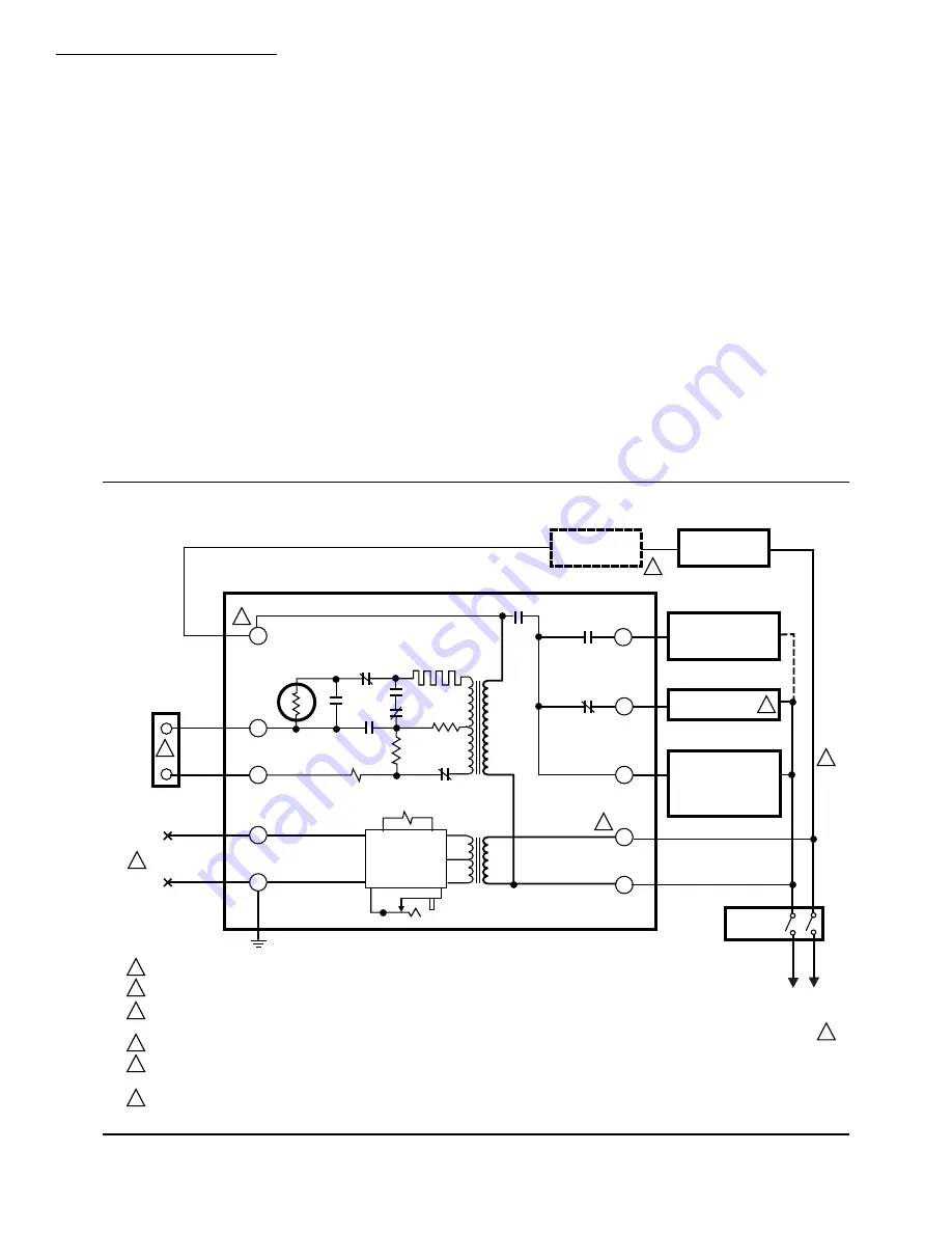
Fig. 5—Internal Schematic of RA890G (Typical External Connections Included).
L1
(HOT)
L2
2
5
1
2
6
4
3
3
1
2
3
4
5
6
PROVIDE DISCONNECT MEANS AND OVERLOAD PROTECTION AS REQUIRED.
RA890G TERMINALS 1 AND 6 MUST BE POWERED.
MAY USE LINE OR LOW VOLTAGE CONTROLLER. IF LINE VOLTAGE CONTROLLER IS USED, CONNECT IT BETWEEN THE LIMIT
CONTROLLER NAD TERMINAL 6. JUMPER T-T.
FOR INTERMITTENT IGNITION CONNECT TO TERMINAL 3.
MINIPEEPER DETECTORS ARE POLARITY SENSITIVE—BLUE LEAD MUST BE CONNECTED TO THE F TERMINAL;
WHITE LEAD CONNECTED TO THE G TERMINAL.
ALL WIRING MUST BE NEC CLASS 1.
LOW VOLTAGE
CONTROLLER
TO FLAME
DETECTOR
THERMISTOR
1K
(LOAD RELAY)
2K (FLAME RELAY)
ELECTRONIC
AMPLIFIER
NETWORK
LINE VOLTAGE
CONTROLLER
LIMIT
CONTROLLER
MAIN GAS VALVE
OR SECOND STAGE
OIL VALVE (IF USED)
INTERRUPTED
IGNITION
PILOT GAS VALVE,
OR BURNER MOTOR
AND DELAYED OIL
VALVE; INTERMITENT
IGNITION
MASTER
SWITCH
POWER
SUPPLY
TEST
JACK
TR2
SAFETY
SWITCH
2K3
1K2
2K4
SAFETY
SWITCH
HEATER
1K1
TR1
2K2
2K1
M8721
5
4
3
1
2
G
F
T
T
6
BLUE
WHITE
1K3
1K4
RA890G
Summary of Contents for RA890G
Page 11: ...11 60 2035 9 ...


