


14
www.honeywell.com
PW6K1ICE Wiring and Setup
Relay Circuit Wiring
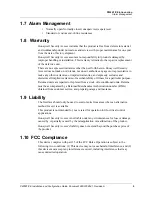
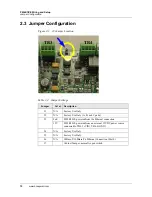
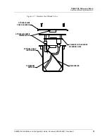
Figure 2-5: Input Circuit Wiring
2.11 Relay Circuit Wiring
Two relays are provided for controlling door lock mechanisms or alarm signaling. The
relay contacts are rated at 2A @ 30VDC, dry contact configuration. Each relay has a
Common pole (C), a Normally Open pole (NO) and a Normally Closed pole (NC).
When you are controlling the delivery of power to the door strike, the Normally Open
and Common poles are used.
When the power to unlock the door is removed temporarily, as with a mag lock, the
Normally Closed and Common poles are used. Check with local building codes for
proper egress door installation.
Note:
Door lock mechanisms can generate feedback to the relay circuit and that can
cause damage and premature failure of the relay. For this reason, it is recommended
that either a diode or MOV (metal oxide varistor) be used to protect the relay. The wire
should be of sufficient gauge to avoid voltage loss.
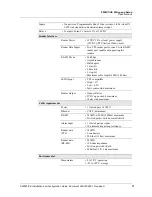
1K,1%
1K,1%
1K,1%
1K,1%
Standard Supervised Circuit,
Normally Closed Contact
Standard Supervised Circuit,
Normally Open Contact
Unsupervised Circuit,
Normally Open Contact
Unsupervised Circuit,
Normally Closed Contact
IN2
IN1
TB1
1
}