


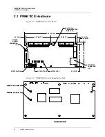


PW6K1ICE Wiring and Setup
Terminal Connections
PW6K1ICE Installation and Configuration Guide
,
Document
800-07985V1, Revision A
9
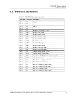
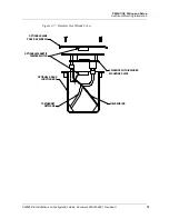
2.2 Terminal Connections
Table 2-1: PW6K1ICE Terminal Connections
Terminal
Acronym Description
TB1-1
IN1
Input 1
TB1-2
IN1
TB1-3
IN2
Input 2
TB1-4
IN2
TB2-1
VO
Reader 1 Power Output - 12VDC
TB2-2
LED
Reader 1 LED Output
TB2-3
BZR
Reader 1 Buzzer Output
TB2-4
CLK
Reader 1 CLK/Data 1/TR+
TB2-5
DAT
Reader 1 DAT/Data 0/TR-
TB2-6
GND
Reader 1 Ground
TB3-1
LED
Reader 2 LED Output
TB3-2
BZR
Reader 2 Buzzer Output
TB3-3
CLK
Reader 2 CLK/Data 1 Input
TB3-4
DAT
Reader 2 DAT/Data 0 Input
TB4-1
VO
Auxiliary Power Output - 12VDC
TB4-2
GND
Auxiliary Power Output Ground
TB4-3
VIN
Input Power - 12VDC (from local power supply)
TB4-4
GND
Input Power Ground
TB5-1
NO
Relay K1 - Normally Open Contact
TB5-2
1-C
Relay K1 - Common Contact
TB5-3
NC
Relay K1 - Normally Closed Contact
TB5-4
NO
Relay K2 - Normally Open Contact
TB5-5
2-C
Relay K2 - Common Contact
TB5-6
NC
Relay K2 - Normally Closed Contact