


PW6K1ICE Wiring and Setup
DIP Switch Configuration
PW6K1ICE Installation and Configuration Guide
,
Document
800-07985V1, Revision A
11
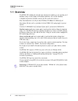
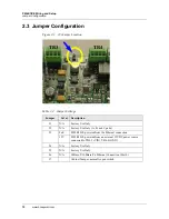
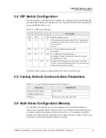
2.4 DIP Switch Configuration
The four switches on S1 DIP switch configure the operating mode of the PW6K1ICE
processor. DIP switches are read on power-up except where noted. Pressing switch S2
causes the PW6K1ICE to reset.
All other switch settings are unassigned and are reserved for future use.
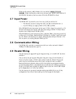
2.5 Factory Default Communication Parameters
2.6 Bulk Erase Configuration Memory
Use the bulk erase function to erase all configuration and cardholder databases.
When power is applied with S1 switches set to 1 and 2 ON and 3 and 4 OFF, there is a
10-second window when memory is erased if switch 1 or 2 is changed to the OFF
position. The LEDs flash the following pattern when in the reset window: LED 1 and
2 and LED 3 and 4 flash alternately at 0.5 second rate.
Table 2-3: DIP Switch Settings
1
2
3
4
Description
OFF
OFF
X
OFF
Normal operating mode.
ON
X
X
X
After initialization, enable default User Name (admin)
and Password (password). The switch is read on the
fly, no need to
re-boot.
OFF
ON
X
OFF
Use factory default communication
parameters.
ON
ON
X
OFF
Use OEM default communication
parameters. Contact system manufacture for details.
See Bulk Erase below.
X
X
ON
X
Disable TLS (Transport Layer Security) secure link.
Switch is read only during the login. Ask your network
administrator about this setting.
Table 2-4: Factory Default Communication Parameters
Parameter
Default Value
Network static IP address
192.168.0.251
Communication address
0
Host port
IP server, no encryption, port 3001