


PW6K1ICE Wiring and Setup
Input Circuit Wiring
PW6K1ICE Installation and Configuration Guide
,
Document
800-07985V1, Revision A
13
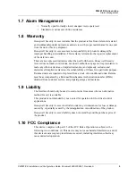
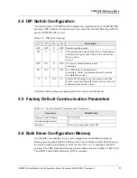
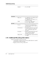
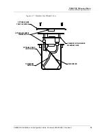
Figure 2-4: Reader Wiring Diagram
2.10 Input Circuit Wiring
Typically, these inputs are used to monitor door position, request to exit, or alarm
contacts. Input circuits can be configured as unsupervised or supervised. When
unsupervised, reporting consists of only the open or closed states.
When configured as supervised, the input circuit will report not only open and closed,
but also open circuit, shorted, grounded, and foreign voltage.
Note:
Grounded and foreign voltage states are not a requirement of UL 294 and
therefore not verified by UL.
A supervised input circuit requires two resistors be added to the circuit to facilitate
proper reporting. The standard supervised circuit requires 1K Ohm, 1% resistors and
should be located as close to the sensor as possible. Custom end of line (EOL)
resistances may be configured via the host software.
The input circuit wiring configurations shown are supported but may not be typical:
RED (1)
WHT (3)
GRN (2)
BRN (4)
BLK (6)
ORG (5)
VO
LED
BZR
CLK/D1
DAT/D0
GND
MR-10/20 READER
1
TB2
FIRST READER PORT
DATA1/DATA0 OR CLOCK/DATA
MR-10/20 READER
SECOND READER PORT
DATA1/DATA0 OR CLOCK/DATA
WHT (3)
RED (1)
GRN (2)
ORG (5)
BRN (4)
BLK (6)
TB4
1
1
TB3
CLK/D1
GND
VO
DAT/D0
LED
BZR