


62
NFW-50X Manual —
P/N LS10129-001NF-E:C 7/25/2018
Programming
Master Programming Level
Edit Module Screen for Control Modules
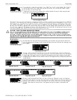
The programmer can change a module’s existing or factory default programming by pressing
3
in the Mod-
ules Screen. The following screen will be displayed:
A flashing cursor will appear in the position of the first asterisk to the left.
The programmer keys in the three digit module address, such as
002
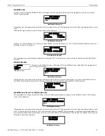
. When the last digit is keyed-in, if the selected address corresponds
to a
control
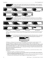
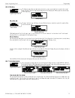
module, a screen displaying information about the control module with the selected address will be displayed as illustrated in
the following:
In the preceding example:
Normal - indicates that the module with the selected address is physically installed on the SLC and communicating with the
control panel (enabled)
ugh.<ADJ><NOUN> - represents the adjective and noun, which have been programmed, describing the location of the
displayed device
Control - indicates that the selected module is a control module
S or * - represents Silenceable (S) or Nonsilenceable (*)
W or * - represents Waterflow Timer Delay (W = Waterflow Timer Delay enabled, * = Waterflow Timer Delay disabled)
ZNNN - represents the first of five possible software zones that the module is assigned to (NNN = the three digit zone number
from 000 - 049)
1M002 - represents the Loop, Device type and Device address (1=SLC Loop, M=Module and 002 = Module Address 02)
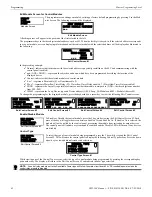
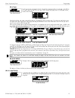
To change the programming for the displayed module, press the keyboard
down
arrow key to view the following Edit Control screens:
Enable/Disable Module
To Enable or Disable the control module, press the
1
key while viewing the Edit Control Screen #2. Each
press of the key will toggle the screen between
Enabled Yes
and
Enabled No
. If
Enabled No
is selected, the
module will not be polled by the control panel, preventing the module from activating its output devices.
The control panel will indicate a system trouble condition and the Disable LED will turn on if any devices
are disabled.
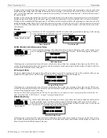
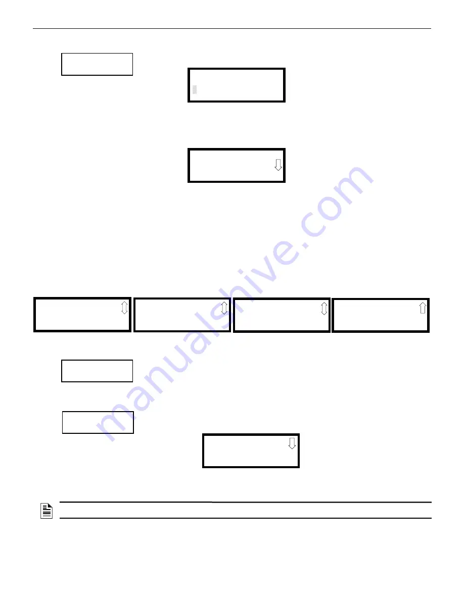
Control Type
To select the type of control module being programmed, press the
2
key while viewing the Edit Control
Screen #2. This will cause the control panel to display the following Control Type Screens. Press the down
arrow key to view additional screens and selections.
While viewing one of the Control Type screens, select the type of control module being programmed by pressing the corresponding key-
pad number key. The display will return to the Edit Control Screen #2 and indicate the new type selection.
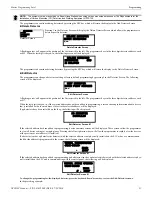
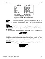
MODULES
1=ADD
2=DELETE
3=EDIT
Modules Screen
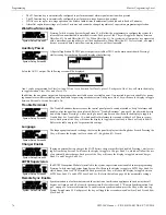
EDIT MODULE
ENTER MODULE ADDRESS
Edit Module Screen
NORMAL CONTROL
<ADJ><NOUN>
ZNNN
1M002
Edit Control Screen #1
EDIT CONTROL
1=ENABLED YES
2=TYPE CONTROL
3=SILENCEABLE YES
Edit Control Screen #2
EDIT CONTROL
1=WALKTEST YES
2=ZONE ASSIGNMENT
000
Edit Control Screen #3
EDIT CONTROL
1=NOUN/ADJECTIVE
2=DESCRIPTION
Edit Control Screen #4
EDIT CONTROL
1=CTRL MOD DLY NO
WIRELESS NO
Edit Control Screen #5
EDIT CONTROL
1=ENABLED
2=TYPE CONTROL
3=SILENCEABLE
Edit Control Screen #2
EDIT CONTROL
1=ENABLED
2=TYPE CONTROL
3=SILENCEABLE
Edit Control Screen #2
CONTROL TYPE
FUTURE USE
2=BELL-CIRCUIT
3=HORN-CIRCUIT
Control Type Screen #1
NOTE:
A control relay module set to the Resettable Power type will follow the main circuit board 24 VDC resettable power unless the
control relay module is disabled.