


INTELLIDOX DOCKING MODULE USER MANUAL || DETECTOR OPERATIONS
HONEYWELL
PAGE 57 OF 119
Ensuring proper operation of the IntelliDoX BW Clip4 module
After performing a bump test or calibration, remove the detector from the IntelliDoX
docking module to allow any residual gas to clear.
Leaving the detector in the docking module may cause it to fail the calibration. If a detector
is bump tested and then a calibration is performed without removing it from the docking
module, residual gas may cause the calibration to fail.
Calibrating a Detector
You may use Safety Suite Device Configurator software to configure a detector to
automatically perform calibration on insertion if the sensor calibration is overdue. When a
compatible detector is inserted into the module and the calibration is overdue, then
calibration starts automatically once the detector is recognized. Progress screens are
displayed while the tests are performed.
1. Insert a compatible detector into the module. The LCD changes to gray and
Detector
identification
is displayed.
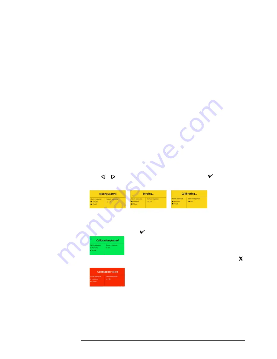
2. When the module is configured to perform a calibration on overdue sensors and other
procedures on insertion and the calibration is overdue, the LCD changes to yellow
and Testing Alarms is displayed after the detector is recognized. Go to step 6.
3. When the module is configured to perform calibration and other procedures on
insertion and the calibration is NOT overdue, the other procedures are performed
after the detector is recognized. After the procedures are completed, What do you
need to do? is displayed on the LCD. Go to step 5.
4. When the module is NOT configured to perform calibration or other procedures on
insertion, detector operations menu and
What do you need to do?
are displayed
after the detector is recognized. Go to step 5.
5. Press or to scroll to
Calibrate my detector
, and then press . The
LCD changes to yellow and the calibration begins. Calibration begins. Progress
screens are displayed while the tests are performed.
6. If the module is configured via Safety Suite Device Configurator software to
automatically download datalogs, the detector datalogs are transferred to the module
after the calibration is complete.
7. When the calibration is successful, the LCD changes to green and
Calibration
passed
is displayed. Press to return to the detector operations menu.
8. If the calibration fails, the LCD changes to red and
Calibration failed
is displayed.
indicates failed alarm and/or sensor test.
9. To understand how to respond appropriately to failed tests, refer to the appropriate
detector operator manual.