SYSTEM DESCRIPTION AND INSTALLATION MANUAL
HS--700 High Speed Data System
23--20--33
30 Aug 2002
Use or disclosure of information on this page is subject to the restrictions in the proprietary notice of this document.
Page 3--6
3. Electrical Installation
A. HSU
(1) General
(a) The HSU interface block diagram is shown in Figure 3-6.
Figure 3-6. HSU Interface Block Diagram
(2) HSU X1 Connector
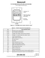
(a) The HSU front panel X1 connector is an interface to a PC for maintenance
purposes. The X1 connector is a 9--pole female sub--D filter connector. The HSU
X1 connector layout is shown in Figure 3-7. Table 3-1 gives the pin assignments
of the X1 connector.
(b) The HSU has two CMT interfaces, one on the X1 connector (CMT1) and one on
the X2 connector (CMT2). Both interfaces support EIA/TIA--232--E standard and
can also be used as a printer interface. Only the CMT1 on the X1 connector can
be used for software uploading. The interfaces are configured as DCE on the
HSU.
(c) The CMT1 interface (pins 2, 3, and 5) has a Baud rate of 9,600 bps or 115.2
kbps for software uploading. There are eight data bits and one stop bit with no
parity.
(d) The HSU X1 connector contains an input pin (pin 4) to disable the X2 rear
connector CMT2 interface. If the rear connector CMT2 interface is connected to
a terminal, it is diabled when using the front connector CMT1 since both CMTs
share the same internal serial I/O port.
(e) The rear connector CMT2 interface is disabled by connecting X1 connector pin 4
to --12 V dc. This is done by mounting a jumper from pin 4 to pin 6 in the serial
cable plug. If a fully populated RS--232 serial cable is used, no jumper is needed.


