SYSTEM DESCRIPTION AND INSTALLATION MANUAL
HS--700 High Speed Data System
23--20--33
30 Aug 2002
Use or disclosure of information on this page is subject to the restrictions in the proprietary notice of this document.
Page 3--8
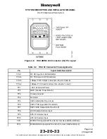
Figure 3-8. HSU ARINC 404 Connector (X2) Pin Layout
Table 3-2. HSU X2 Connector Pin Assignments
Pin
Signal Name/Description
TP A1
RF RX Input from DLNA/Splitter
TP A2
RF TX Output to HPA/Combiner
TP A3
10Base--T RX Output to User (RJ--45 pins 3 and 6)
TP A4
10Base--T TX Input from User (RJ--45 pins 1 and 2)
TP1
+28 V dc Ground Power
TP2
GND (Ground Power Return)
TP3
Chassis Ground
TP4
Not Used
TP5
CMT2 GND (EIA/TIA--232--E)
TP6
CMT2 TXD Input (EIA/TIA--232--E)
TP7
CMT2 RXD Output (EIA/TIA--232--E)
TP8
HSU Disable Discrete Input
TP9
ATE #1 Discrete Input
TP10
ATE #2 Discrete Input
TP11
MPDS TXD Input (EIA/TIA--232--E) from User (DB25--2/DE9--3)
TP12
MPDS RXD Output (EIA/TIA--232--E) to User (DB25--3/DE9--2)


