


Description
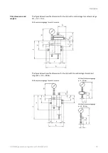
HON 5020 gas pressure regulator with HON 630 pilot
9
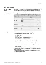
There are three different versions of the individual control stage component installed in the
HON 630 pilot, with the specific version used depending on the control stage’s setpoint range
(W
d
):
Setpoint range W
d
Design
0.3 to 1 bar
With larger diaphragm assembly
0.5 to 40 bar
With diaphragm assembly
10 to 90 bar
With metal bellows assembly
The optional load limiting stage for the HON 630 pilot always features a diaphragm assembly
regardless of the control
stage’s setpoint range (W
d
).
The
technical specifications
and the
Maintenance
section, as well as the spare parts lists and
spare parts drawings in the
appendix
, describe all the gas pressure regulator versions and all
the models corresponding to the standard for this device type. Special-purpose versions are
identified with “SO” in the inspection certificate, which is included with the gas pressure
regulator.
The remaining sections in this user manual mostly use the version with the two-stage pilot
with a diaphragm assembly as a reference. However, other versions and models will be
covered specifically as well when there are important differences that need to be pointed
out.
If you have trouble understanding the information in this documentation, contact the manu-
facturer without fail before starting any work on the device.
2.3
Labels/Markings
Illegible information on the device poses a risk of injury due to resulting erroneous opera-
tion, use, or installation.
Labels, as well as inscriptions and stamping on the device, can eventually become soiled or
otherwise unrecognizable to such an extent that users will not be warned effectively of
hazards and may be unable to follow required operating instructions. This will pose a risk of
injury.
Make sure to always keep all relevant labels in good condition so that they will be easily
legible.
Immediately replace damaged and missing labels.
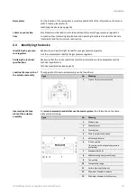
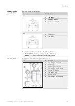
The following labels/marki
ngs can be found on the actuator assembly’s casing:
Figure
No.
Meaning
1
Nameplate
2
Body part number
3
Batch number
Foundry code
4
CE PIN
(only if the unit has been granted a CE type
approval)
5
Body nominal size
6
Arrow indicating the direction of flow
Control stage models
Models for the optional
load limiting stage
Versions and designs in
this user manual
Illegible labels
Labels on the HON 5020
actuator assembly


