


Basics
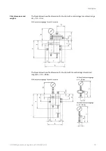
for installing the device in a pipe
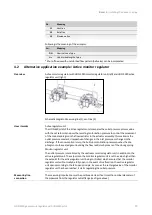
HON 5020 gas pressure regulator with HON 630 pilot
29
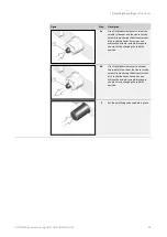
No.
Meaning
11
Vent line
12
Relief line
13
Blowdown line
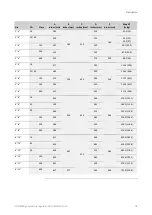
Following is the meaning of the acronyms:
Acr.
Meaning
DN
Nominal size of pipe
L
uR
Undisturbed length of pipe
* Shut-off device with undisturbed flow pattern (ball valve) can be incorporated
4.2
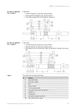
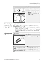
Alternative application example: Active monitor regulator
Active monitor regulator with HON
5020 monitor regulator unit (left) and HON
5020 active
regulator unit (right):
Schematic diagram: Measuring line (1), vent line (2)
Active regulator unit:
The HON
630 pilot of the active regulator unit compares the outlet pressure process value
with the set setpoint and uses the resulting motorization pressure to control the movement
of the main diaphragm on the flow restrictor in the actuator assembly. This maintains the
outlet pressure constant, irrespective of changes in the inlet pressure or changes in the
discharge. If the consumption is zero, the built up motorization pressure pushes the dia-
phragm onto the seat edge surrounding the flow restrictor by means of the closing spring.
Monitor regulator unit:
The outlet pressure is monitored by the upstream monitor regulator unit in addition to the
active regulator unit. The setpoint on the monitor regulator unit is set to a value higher than
the setpoint for the active regulator unit being controlled, which ensures that the monitor
regulator unit will normally be fully open. In the event of malfunction, the active regulator
unit opens according to the fail-open principle. As soon as the set target value of the monitor
regulator unit has been reached, it starts regulating the outlet pressure.
The measuring impulse line must be positioned at least five times the nominal diameter of
the pipework from the regulator outlet flange (see figure above).
Overview
How it works
Measuring line
connection


