


Description
HON 5020 gas pressure regulator with HON 630 pilot
14
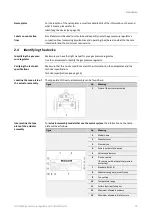
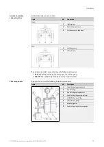
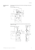
The pilot features the following fittings:
Figure
No.
Description
1
Port for inlet pressure line
Ø10, M 14 x 1.5
2
Inlet pressure gauge fitting
3
Loading pressure gauge fitting
4
Port for outlet pressure sensing line
Ø12, M 14 x 1.5
Optionally with pressure gauge for
outlet pressure and protection against
overpressure
5
Port for outlet pressure process line
6
Vent line connection
Ø12, M 14 x 1.5 (ambient pressure com-
pensation)
7
Inlet pressure fitting
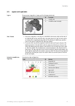
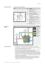
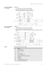
Figure
Color
Meaning
Inlet pressure
Loading
pressure
Motorization
pressure
Outlet pres-
sure
Atmospheric
pressure
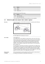
The inlet pressure is conveyed into the load limiting stage via the fine mesh filter.
The outlet pressure is conveyed into the control stage and produces a force component
that acts on the double diaphragm system from above.
The pilot’s set screw is used to tighten the pilot spring, producing a force component
that acts on the control stage’s double diaphragm system from below.
The force components being exerted on the double diaphragm system are used by the
system in order to compare the setpoint and the process value. Depending on the out-
let pressure and on the set setpoint, a small/large gap relative to the load limiting stage
will be cleared. This, in turn, will result in an accordingly low/high loading pressure be-
ing passed on to the load limiting stage.
Inside the load limiting stage, the double diaphragm system (much like the control
stage) performs a setpoint/process value comparison between the loading pressure
acting from above and the outlet pressure acting from below.
Pilot connection lines
Pilot pressure
sections
How the pilot works


