


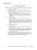


Set Up and Calibration Procedures
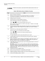
Setting End-of-Travel Limit Switches
80
HercuLine™ 2000 Series Actuator - Installation, Operation and Maintenance Manual
Revision 7
7/08
ATTENTION
Make sure you do not to set the switches too close to the hard stop.
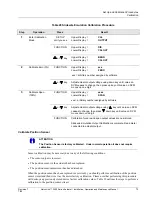
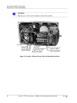
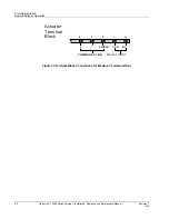
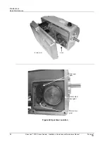
Relay #1
Relay #2
Relay #3
Relay #4
Aux switch #1
Aux switch #2
Aux switch #3
Aux switch #4
End of travel switch #1
(stops CW rotation)
End of travel switch #2
(stops CCW rotation)
Relay PWAs
Figure 31 Location of End-of-Travel Limit and Auxiliary Switches