


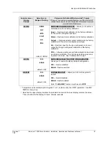

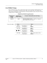
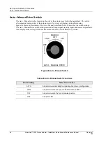


Set Up and Calibration Procedures
Calibration
Revision 7
HercuLine™ 2000 Series Actuator - Installation, Operation and Maintenance Manual
67
7/08
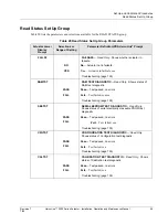
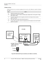
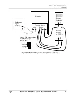
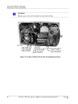
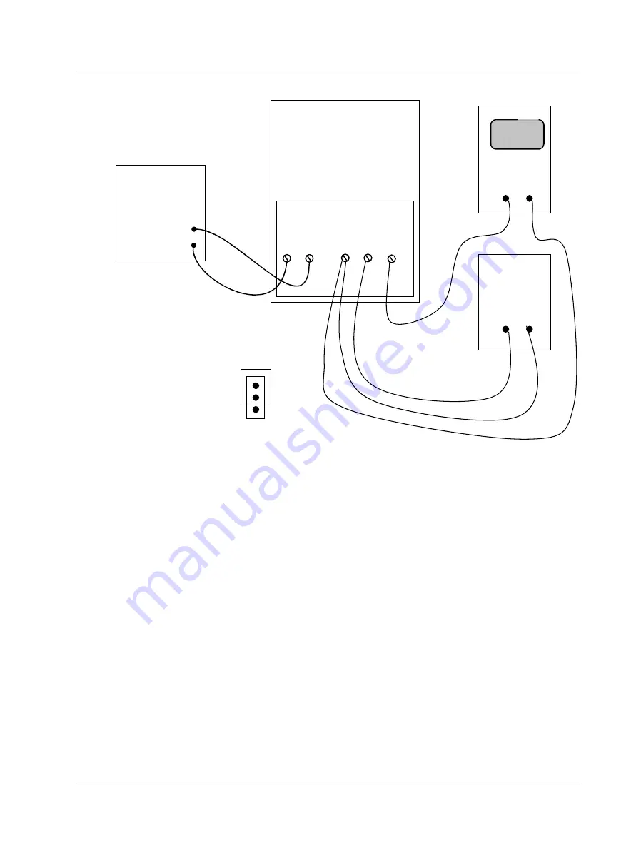
Actuator
Input
5 4
-
+
Output
2 1 3
-
+
+
-
Calibrated
Signal
Source
Digital
Voltmeter
+ -
FB
Terminal Block
Power
Supply
1-18 VDC
+ -
Internal 250 ohm resistor
settable through
Jumper W2
Current
Voltage
Figure 26 Calibration Wiring Connections (slidewire emulation)