


Set Up and Calibration Procedures
Calibration
66
HercuLine™ 2000 Series Actuator - Installation, Operation and Maintenance Manual
Revision 7
7/08
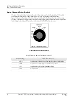
Calibration Set up
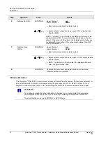
Follow the steps below to set up the test equipment and actuator to verify calibration or perform calibration
procedures.
Step
Action
1
Determine input type (current or voltage).
2
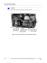
Set jumper W2 on main CPU board according to type of signal source. See Figure 27 on page
68 for jumper location.
3
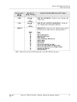
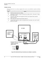
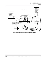
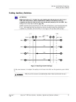
Connect the copper leads from the signal source to the input terminals of the actuator as
shown in Figure 25.
4
Place signal source output at zero and switch power on.
5
Connect a 250 ohm resistor across the Output terminals of the actuator and connect the DVM
leads to the terminals.
Actuator
Input
5 4
-
+
Output
2 1
-
+
+
-
Calibrated
Signal
Source
Digital
Voltmeter
+ -
Terminal Block
Internal 250 ohm resistor
settable through
Jumper W2
Current
Voltage
250 ohm
resistor
(supplied)
Figure 25 Calibration Wiring Connections (non-slidewire emulation)