background image

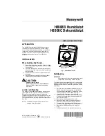
H8908B HUMIDISTAT/H8908C DEHUMIDISTAT

3

69-1341EF

WIRING

CAUTION

Personal Injury Hazard.
Power supply can cause electrical shock and 
injury.

Disconnect power supply before installation or 
servicing.

All wiring must comply with applicable local codes, 
ordinances and regulations. Make wiring connections 
according to humidifier (or dehumidifier/ventilator) 
instructions, if available; otherwise, see typical wiring 
diagrams in Fig. 5 through 12.

IMPORTANT

Select models of fan centers include humidifer 
taps so the current sensing relay or sail switch 
is not needed. 

If not using a current sensing relay or sail 
switch, the humidifier must be energized during 
blower motor cycles for proper operation. 

On multispeed blower applications, do not wire 
the high voltage side of the transformer to the 
same power source that services the furnace 
blower. Premature transformer burnout can 
occur. 

On HE360 fan powered humidifier models, only 
the two yellow wires are connected to the con-
trol. The remaining two red wires are only used 
with electronic humidity controls. 

Fig. 5. Typical wiring diagram for 

system with fan interlock.

Fig. 6. Typical wiring diagram for system 

with 2-speed fan motor.

Fig. 7. Typical wiring diagram of current 

sensing relay with humidifier.

Fig. 8. Typical wiring diagram 
of sail switch with humidifier.

Fig. 9. Typical wiring diagram for steam humidifiers.

1

1

2

PROVIDE DISCONNECT MEANS AND OVERLOAD PROTECTION 
AS REQUIRED.

24 VAC WIRING. 

2

HUMIDIFIER

TRANSFORMER

FURNACE
FAN
MOTOR

H8908B

FAN CONTROL

L1
(HOT)

L2

M13368

POWER
SUPPLY

1

1

H

L

C

2

POWER SUPPLY.  PROVIDE DISCONNECT MEANS AND OVERLOAD 
PROTECTION AS REQUIRED.

24 VAC WIRING. 

2

HUMIDIFIER

TRANSFORMER

2-SPEED
FAN
MOTOR

DPST
SWITCHING
RELAY

H8908B

FAN CONTROL

L1
(HOT)

L2

M13384

POWER
SUPPLY

M13386

L1 
(HOT)

L2

1

2

1

2

POWER SUPPLY.  PROVIDE DISCONNECT MEANS 
AND OVERLOAD PROTECTION AS REQUIRED.

24V WIRING.

HUMIDIFIER

TRANSFORMER

WATER 
SOLENOID
LEAD WIRE

CURRENT
SENSING
RELAY

C

LO

HI

H8908B

M13385

L1 
(HOT)

L2

1

2

1

2

POWER SUPPLY.  PROVIDE DISCONNECT MEANS 
AND OVERLOAD PROTECTION AS REQUIRED.

24V WIRING.

HUMIDIFIER

TRANSFORMER

H8908B

SAIL
SWITCH

M13387

1

1

1

FOLLOW THE INSTALLATION INSTRUCTIONS 
INCLUDED WITH THE STEAM HUMIDIFIER 
TO WIRE THE SYSTEM FAN.

NOTE: 

HUMIDIFIER

H8908B

TO 
SYSTEM
FAN 

HUMIDISTAT
TERMINALS

FAN WIRING
TERMINALS

24V WIRING.

Summary of Contents for H8908B Humidistat

Page 1: ...ext to the T8600 The H8908 can also be mounted at any other convenient location in the living area or equipment room See Fig 1 NOTE The H8908 electrical connections are not shared with the thermostat Fig 1 H8908B Humidistat Wall Mounting IMPORTANT Mount the control in an area with average room temperature and average relative humidity The following mounting instructions are for mounting the H8908 ...

Page 2: ...lace the H8908 case IMPORTANT Use 18 to 22 gauge wire for proper wiring Fig 4 Positioning return air duct template M13370 THERMOSTAT WALLPLATE MOUNTING TEMPLATE MOUNTING HOLES 2 WIRING HOLES FOR MOUNTING ON RIGHT USE LEFT HOLES FOR MOUNTING ON LEFT ALTERNATE LOCATION RETURN AIR RETURN AIR 6 in 152 mm MINIMUM 15 in 381 mm MINIMUM BEST LOCATION RETURN AIR DUCT M13369 CAUTION Equipment Damage Hazard ...

Page 3: ...rols Fig 5 Typical wiring diagram for system with fan interlock Fig 6 Typical wiring diagram for system with 2 speed fan motor Fig 7 Typical wiring diagram of current sensing relay with humidifier Fig 8 Typical wiring diagram of sail switch with humidifier Fig 9 Typical wiring diagram for steam humidifiers 1 1 2 PROVIDE DISCONNECT MEANS AND OVERLOAD PROTECTION AS REQUIRED 24 VAC WIRING 2 HUMIDIFIE...

Page 4: ...To reduce the relative humidity reduce the setpoint approximately three percent relative humidity every 24 hours To increase the relative humidity increase the sepoint approximately three percent relative humidity every 24 hours Setpoint Adjustment Set the humidity setpoint according to the prevailing outdoor temperature See Table 1 for recommended settings Table 1 Recommended Humidity Controller ...

Page 5: ...ompris afin de d installer le H8908 près d un T8600 Le H8908 peut également être installé à n importe quel endroit dans la maison ou encore dans une salle d installations techniques Voir Fig 1 REMARQUE Le H8908 et le thermostat ne partagent pas le même câblage Fig 1 Humidistat H8908B Installation au mur IMPORTANT Installer le régulateur dans un endroit où la température et l humidité relative ambi...

Page 6: ... couvercle du H8908 IMPORTANT Utiliser du fil de calibre 18 à 22 pour un raccordement adéquat Fig 4 Positionnement du gabarit de la gaine de reprise MF13370 PLAQUE DE MONTAGE DU THERMOSTAT GABARIT TROUS DE FIXATION 2 TROUS POUR LE RACCORDEMENT ET INSTALLATION À DROITE UTILISER LES TROUS DE GAUCHE POUR UNE INSTALLATION À GAUCHE AUTRE EMPLACEMENT AIR REPRIS AIR REPRIS AU MOINS 152 mm 6 po AU MOINS 3...

Page 7: ...un humidificateur asservi au régulateur du ventilateur Fig 6 Schéma de raccordement type d un système avec un moteur de ventilateur à 2 vitesses Fig 7 Schéma de raccordement type d un relais détecteur de courant et d un humidificateur Fig 8 Schéma de raccordement type d un interrupteur à ailette et d un humidificateur Fig 9 Schéma de raccordement type d humidificateurs à vapeur 1 1 2 ALIMENTATION ...

Page 8: ...midité relative abaisser le point de consigne d environ 3 tous les 24 heures Afin d augmenter l humidité relative hausser le point de consigne de 3 tous les 24 heures Réglage du point de consigne Régler le point de consigne de l humidité selon la température extérieure Consulter le Tableau 1 pour obtenir les réglages recommandés Tableau 1 Réglages recommandés du régulateur d humidité FONCTIONNEMEN...

Reviews: