


3. Configuration
3.7. ALARM Set Up Group
30
EDC201 / EDC202 / EDC203 Product Manual
Revision 2.0
July 2015
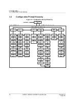
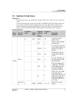
3.7 ALARM Set Up Group
Introduction
An alarm is an indication that an event that you have configured (for example—Process Variable)
has exceeded one or more alarm limits. There is one alarm available for EDC201.There are two
alarms available for EDC202 and EDC203. Each alarm has two Set Points. You can configure each
of these two Set Points to alarm on various controller parameters.
There are two alarm output selections, High and Low. You can configure each Set Point to alarm
either High or Low. These are called single alarms.
You can also configure the two Set Points to alarm on the same event and to alarm both high and
low. A single adjustable Hysteresis of 0 % to 100 % is configurable for the alarm Set Point.
The prompts for the Alarm Outputs appear whether or not the alarm relays are physically present.
This allows the Alarm status to be shown on the display.
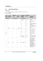
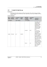
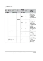
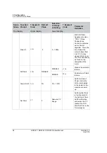
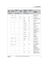
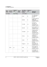
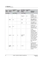
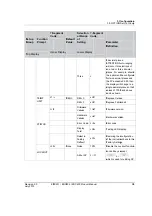
Function Prompts
Set up
Group
Function
Prompt
7-Segment
Code
Default
Value
Selection or
Range of
Setting
7-Segment
Code
Parameter
Definition
Top Display
Upper Display
Lower Display
Alarms
11TYPE
AL11
None
None
NONE
NO ALARM
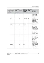
PV
PV
PROCESS VARIABLE
DEV
DEV
DEVIATION
Output
OUT
OUTPUT
MANUAL
Man
ALARM ON MANUAL
MODE
PV RATE
PVRT
PV RATE OF
CHANGE
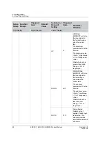
DIG INP
DIN
DIGITAL INPUT
TCWARN
TCWN
THERMOCOUPLE
WARNING
TCFAIL
TCFL
THERMOCOUPLE
FAILING
FSAFE
FS
FAILSAFE
Diagnostic
DIAG
SYSTEM
DIAGNOSTIC
11SEL
SE11
HIGH
HI
HIGH ALARM
LOW
LO
LOW ALARM


