50
Emergency Command Center Manual —
P/N LS10001-000FL-E:G 5/3/2016
Installation
Installation of Option Modules
2.13 Installation of Option Modules
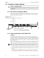
2.13.1 ECC-CE6 Circuit Expander Module
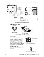
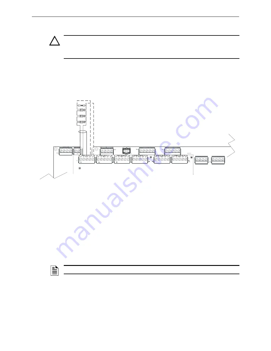
The ECC-CE6 Circuit Expander Module provides connections for up to six Style Z (Class A) or
Style Y (Class B) speaker circuits. Circuits are configured through the web-based programming
utility. Refer to Section 3.2.2 on page 61.
2.13.2 Audio Amplifier Module (ECC-50W-25/70V)
Installation
The optional audio amplifier module can be used to provide a second 50 watt speaker circuit,
increasing the total ECC-50/100 power to 100 watts, or it can be used as a backup amplifier. Refer
to Section 3.2.2 on page 61 for programming the amplifier’s operation. Connectors J1 & J2 of the
audio amplifier module plug into connectors J10 & J11, respectively, located at the upper right of
the main control board.
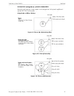
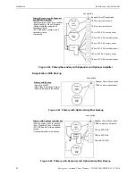
Figure 2.33 shows the installation of a ECC-50W-25/70V onto an ECC-50/100 panel. The optional
amplifier may be programmed and wired for backup or for providing a second audio channel.
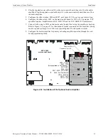
1. Remove mounting screws shown, from the main control board, and save (refer to Figure 2.33).
2. Install four supplied metal standoffs in locations from which mounting screws were removed
3. Secure the Audio Amplifier Module with the screws removed in Step 1. It is important to
secure the module with the metal screws in order to help protect against electrical transients.
!
CAUTION:
DISCONNECT POWER
BEFORE INSTALLING ANY MODULES OR CABLES, MAKE CERTAIN ALL POWER (AC AND DC)
HAS BEEN REMOVED AND BE SURE TO OBSERVE PROPER GROUNDING AND HANDLING
PROCEDURES.
Rev.
ECC-MCB-PCA
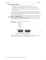
Figure 2.31 Circuit Expander Module Wiring
Style Z (Class A) Circuit
ELR required for Style Y -
Class B only
15K, 1 watt, P/N:ELR-15K
Shield
c
e
6
w
ir
e
.w
m
f
ECC-CE6 mounted onto ECC-50/100
NOTE:
Both the primary and secondary amplifiers must be same voltage output (25V or 70V).
Summary of Contents for ECC-50/100
Page 83: ...Emergency Command Center Manual P N LS10001 000FL E G 5 3 2016 83 Notes ...
Page 95: ...Emergency Command Center Manual P N LS10001 000FL E G 5 3 2016 95 Notes ...
Page 102: ...102 Emergency Command Center Manual P N LS10001 000FL E G 5 3 2016 Notes ...
Page 106: ...106 Emergency Command Center Manual P N LS10001 000FL E G 5 3 2016 Slide in Labels ...
Page 108: ...108 Emergency Command Center Manual P N LS10001 000FL E G 5 3 2016 Slide in Labels ...
Page 114: ...Cut along dotted line ...

