Chapter 6. OPERATION
6-3
■
Display in program operation mode
●
DISP
functions
Output Model No.
Display
0D, 5G, 6D
Display 1
→
Display 2
→
Display 5
→
Display 6
→
Display 7
→
Display 1 (repeated)
2G
Display 1
→
Display 2
→
Display 3
→
Display 5
→
Display 6
→
Display 7
→
Display 1 (repeated)
3D, 5K
Display 1
→
Display 2
→
Display 4
→
Display 5
→
Display 6
→
Display 7
→
Display 1 (repeated)
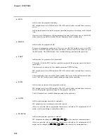
●
Display 1
PV
SP
PV
SP
Program No.
Segment No.
Pattern
tendency
Output states of events 1 to 3, time events 1 to 5
The digit to which SP values can be entered blinks in the MANUAL mode when pro-
grammer functions are selected.
●
Display 2
PV
OUT
PV
Output value (%)
Program No.
Segment No.
Pattern
tendency
Output states of events 1 to 3, time events 1 to 5
The digit to which SP values can be entered blinks in the MANUAL mode when control-
ler functions are selected.
●
Display 3
Program No.
Segment No.
Pattern
tendency
Motor valve opening (%)
Output states of events 1 to 3, time events 1 to 5
F
B
This display is exclusive to 2G output models (output catalog No. appended with 2G).


