


Chapter 7. PARAMETER SETUP
7-41
(A
2
, B
2
)
(A
1
, B
1
)
B-axis
A-axis
1
2
3
4
5
6
7
9
8
10
11
B-axis (output)
Fixed value
(10000, 10000)
A-axis (input)
Fixed value
(-2000, -2000)
(A
3
, B
3
)
(A
2
, B
2
)
(A
1
, B
1
)
(A
3
, B
3
)
(A
2
, B
2
)
(A
1
, B
1
)
B-axis
B-axis
A-axis
A-axis
Excluded
■
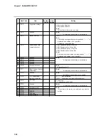
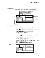
Description of table data settings
●
t
-A
.
1
to
t
-A
.
b
●
t
-b
.
1
to
t
-b
.
b
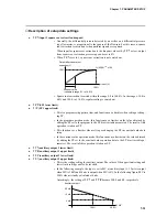
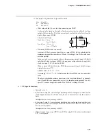
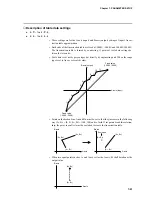
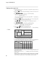
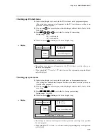
• These settings are for the A-axis (input) and B-axis (output) settings of input 1 linear-
ization table approximation.
• Both ends of the linearization table are fixed at -2000U, -2000U and 10000U,10000U.
The linearization table is formed by connecting 11 points of table data settings be-
tween the two ends.
• Table data is set not by percentages but directly by engineering unit. When the range
type is set to linear, set scaled values.
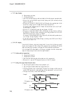
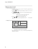
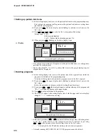
• Points on the broken-line, An and Bn, must be set so that they increase in the following
way (A
1
, B
1
) = (0, 0), (A
2
, B
2
) = (100, 100) and so forth. If set points break this relation-
ship, the point in conflict must be excluded to create the linearization table.
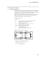
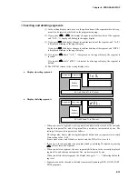
• When two equal points such as A
1
and A
2
are set for the A-axis, B
1
shall be taken as the
output value.