


Chapter 4. WIRING
4-16
4-13 Connecting for Communications
Some controller models support the RS-485 communications interface. Select the RS-485 communications models
by selected the required catalog No.
Connect as follows.
The DCP301 operates as a slave station.
■
RS-485 interface
57
58
59
60
61
SDA
SDB
RDA
RDB
SG
Add-on terminal base
• Multi-drop connection of slave stations is possible.
• Make sure that different addresses are set for each slave station.
• Provide terminating resistor (total of 4 in the case of a 5-wire system connec-
tion) on both ends of the communications path. Use terminating resistor of
150
Ω±
5%, 1/2W min.
• In the case of a 3-wire system connection, short-circuit terminals (57) and (59),
(58) and (60) on the DCP301.
• Do not short-circuit the RDA and RDB, or SDA and SDB terminals. Doing so
might damage the DCP301.
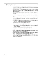
Handling Precautions
Handling Precautions