


Chapter 7. PARAMETER SETUP
7-28
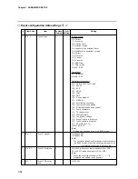
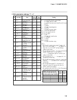
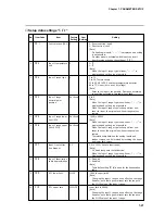
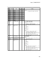
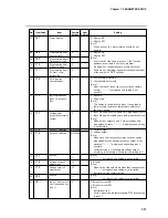
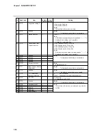
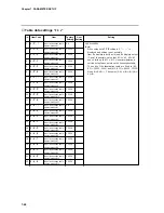
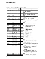
No.
Item Code
Item
Factory
User
Setting
Setting
Setting
11
C
1
1
0
12
C
1
2
0
13
C
1
3
0
14
C
1
4
0
15
C
1
5
0
16
C
1
6
0
17
C
1
7
0
18
C
1
8
0
19
C
1
q
0U
20
C
2
0
1000U
21
C
2
1
–
22
C
2
2
–
23
C
2
3
–
24
C
2
4
–
25
C
2
5
–
26
C
2
6
–
27
C
2
7
–
28
C
2
8
–
29
C
2
q
–
30
C
3
0
–
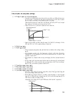
PID set auto-
switching (CH1)
MV setting at input 1
over-range (MV1)
MV at input 1 over-
range (MV1)
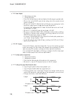
Manual change
mode (MV1)
Preset manual value
(MV1)
MV in READY mode
(MV1, MV1 heat-
cool output)
MV (cool) in READY
mode (MV1 heat-
cool output)
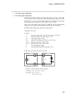
Main output type
(CH1)
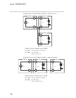
SP1 main output
lower limit (4mA
setting)
SP1 main output
upper limit (20mA
setting)
Unused
Unused
Unused
Unused
Unused
Unused
Unused
Unused
Unused
Unused
0: OFF (PID set segment designation)
1: ON
[Note]
When set to 1, the PID set items in the program are
invalid.
The switching point for auto-switching is set in variable
parameters (
C
P
.
1
1
to
C
P
.
1
7
)
.
0: OFF
1: ON
-10 to 110%
[Note]
When
C
1
2
setting is 0, “– – – –” is displayed and
setting is not possible.
0: Bump-less
1: Preset
[Note]
When the programmer function is selected, operation
is bump-less regardless of the setting of
C
1
4
.
-10 to 110%
[Note]
When
C
1
4
setting is 0, “– – – –” is displayed and
setting is not possible.
-10 to 110%
[Note]
This setting is invalid even if the programmer function
is selected by
C
1
8
setting.
On heat/cool models, this setting functions as the MV
(heat) setting in the READY mode.
-10 to 110%
[Note]
When the model is not a heat/cool model, “– – – –” is
displayed and setting is not possible.
0: MV1 output (controller function)
1: SP1 output (programmer function)
[Note]
When the model is not a 5G output model, “– – – –” is
displayed and setting is not possible.
-1999 to 9999U
[Note]
When the model is not a 5G output model and 8
setting is 0 on a 5G output model, “– – – –” is dis-
played and setting is not possible.
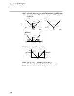
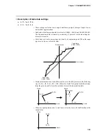
The relationship between the analog outputs and SP1
can be inverted by inverting the upper and lower limit
values.
[Note]
“– – – –” is displayed and setting is not possible.