


LYNX LON PROGRAMMABLE, VAV/UNITARY CONTROLLERS – PRODUCT DATA
EN0Z-0957GE51 R0615
4
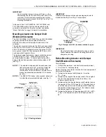
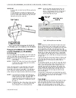
AIR
FLOW
AIR
FLOW
TYPE A DAMPER
TYPE B DAMPER
CW TO OPEN, CCW TO CLOSE
CCW TO OPEN, CW TO CLOSE
Fig. 3. Determining rotation direction (CW or CCW) for
damper opening
Mounting Actuator Onto Damper Shaft
(Models with Actuator)
The unit is shipped with the actuator set to rotate open in the
clockwise (CW) direction to a full 95°. The extra 5° ensures a
full opening range for a 90° damper.
The installation procedure varies depending on the damper
opening direction and angle:
1) If the damper rotates CW to open, and the angle of the
damper open-to-closed is 90°:
a) Manually open the damper fully (rotate CW).
b) Using the DECLUTCH button, rotate the universal
shaft adapter fully CW.
c) Mount the actuator to the VAV damper box and shaft.
d) Tighten the two bolts on the centering clamp (8 mm
wrench; 8...10 Nm torque). When the actuator closes,
the damper rotates CCW 90° to fully close.
2) If the damper rotates CW to open, and the angle of the
damper open-to-closed is 45 or 60°:
a) Manually open the damper fully (rotate CW).
b) The actuator is shipped with the mechanical end-limits
set at 95°. Adjust the two mechanical end-limit set
screws to provide the desired amount of rotation.
Adjust the two set screws closer together to reduce the
rotation travel.
c) Tighten the two mechanical end-limit screws (Phillips
#2 screwdriver; (3.0-3.5 Nm torque).
d) Using the DECLUTCH button, rotate the universal
shaft adapter fully CW.
e) Mount the actuator to the VAV damper box and shaft.
f) Tighten the two bolts on the centering clamp (8 mm
wrench; 8...10 Nm torque).
g) When the actuator closes, the damper rotates CCW
either 45 or 60° to fully close.
3) If the damper rotates CCW to open, and the angle of the
damper open-to-closed is 90°:
a) Manually open the damper fully (rotate CCW).
b) Using the DECLUTCH button, rotate the universal
shaft adapter fully CCW.
c) Mount the actuator to the damper box and shaft.
d) Tighten the two bolts on the centering clamp (8 mm
wrench; 8...10 Nm torque). When the actuator closes,
the damper rotates CW 90° to fully close.
4) If the damper rotates CCW to open, and the angle of the
damper open-to-closed is 45 or 60°:
a) Manually open the damper fully (rotate CCW).
b) The actuator is shipped with the mechanical end-limits
set at 95°. Adjust the two mechanical end-limit set
screws to provide the desired amount of rotation.
Adjust the two set screws closer together to reduce the
rotation travel.
c) Tighten the two mechanical end-limit screws (Phillips
#2 screwdriver; (3.0-3.5 Nm torque).
d) Using the DECLUTCH button, rotate the universal
shaft adapter fully CCW.
e) Mount the actuator to the VAV damper box and shaft.
f) Tighten the two bolts on the centering clamp (8 mm
wrench; 8...10 Nm torque).
g) When the actuator closes, the damper rotates CW
either 45 or 60° to fully close.
IMPORTANT
Special precautions must be taken for dampers that
open in a CCW direction. The actuator is shipped with
its rotation direction set to CW to open, which applies
to the damper direction in steps 1 and 2 above. If the
damper shaft rotates in the CCW direction to open, the
controller software must be programmed to change the
rotation to “Reverse to Open,” which applies to the
damper direction in steps 3 and 4 above.
IMPORTANT
To avoid the possibility of over-pressurizing the duct
work on fan start-up, it is advisable to leave the
dampers in an open position after installation. To
prevent over-pressurization in the duct work on fan
start-up, use the DECLUTCH button (see Fig. 1) to
open the box damper on powered-down controllers. To
declutch, press and hold the DECLUTCH button, thus
disengaging the motor. Turn the damper shaft until the
damper is open and then release the DECLUTCH
button. When power is restored to the controller, the
controller synchronizes the damper actuator, so that
the damper is in the correct position upon start-up.
Mount Controller
NOTE:
The controller may be wired before mounting to a
panel or DIN rail.
Terminal blocks are used to make all wiring connections to
the controller. Attach all wiring to the appropriate terminal
blocks (see section “Wiring” on page 7).
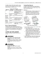
See Fig. 4 and Fig. 7 for panel mounting dimensions. See
Fig. 8 for DIN rail mounting.


