


LYNX LON PROGRAMMABLE, VAV/UNITARY CONTROLLERS – PRODUCT DATA
EN0Z-0957GE51 R0615
12
1 2 3 4 5 6 7 8 9 0 1 2 3 4 5 6 7 8 9 0
2 2 2 2 2 2 2 2 2 2 3 3 3 3 3 3 3 3 3 4
1 2 3 4 5 6 7 8
1
1 1 1 1 1 1 1 1 1 2
1
2 3 4 5 6 7 8 9 0
0
9
CLLYUL6438S
24
V
A
C
24
V
AC
CO
M
E G
N
D
SH
L
D
S
BUS
1
S
BUS
2
NE
T-
1
NE
T-
2
DO
-1
DO
-2
CO
M
CO
M
CO
M
CO
M
DO
-3
DO
-4
DO
-5
DO
-6
DO
-7
DO
-8
AO
-1
AO
-2
AO
-3
DI
-1
DI
-2
DI
-3
DI-
4
20VD
C
UI
-1
UI
-2
UI
-3
UI-
4
UI
-5
UI-
6
CO
M
CO
M
CO
M
CO
M
CO
M
CO
M
24VAC
24VAC
COM
1
PWM VALVE ACTUATOR
4
PWM OUTPUT FROM
CONTROLLER
PWM (H 24 VAC)
T5
T6
C
B
W
R
24 (N)
24 (H)
PWM VALVE ACTUATOR
PWM OUTPUT FROM
CONTROLLER
PWM (H 24 VAC)
T5
T6
C
B
W
R
24 (N)
24 (H)
4
2
3
2
1
3 4
ON
OFF
ML7984B
CONFIGURATION DIP SWITCHES
(LOCATED ADJACENT TO THE
INPUT TERMINAL BLOCK)
PERIPHERAL HEAT
VALVE ACTUATOR
ML7984B REHEAT
VALVE ACTUATOR
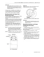
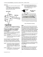
Fig. 17. Controller wiring diagram (CLLYUL6438S shown)
for typical PWM heat and PWM peripheral heat valve
actuator
Ensure that the Configuration DIP Switch is set as shown in
Fig. 17. Switches 1 through 3 set the timing of the ML7984B
valve actuator to match the controller outputs (min. 0.1 sec;
max. 25.6 sec). Switch 4 determines the action of the actuator
(OFF = direct acting, ON = reverse acting).
NOTE 1:
Earth ground wire length should be held to a
minimum. Use the heaviest gauge wire available,
up to 14 AWG (2.0 mm
2
), with a minimum of 18
AWG (1.0 mm
2
), for earth ground wire.
NOTE 2:
Turn power OFF before setting the DIP switches.
NOTE 3:
Ensure that all transformer / power wiring is as
shown. Reversing terminations will result in
equipment malfunction.
1 2 3 4 5 6 7 8 9 0 1 2 3 4 5 6 7 8 9 0
2 2 2 2 2 2 2 2 2 2 3 3 3 3 3 3 3 3 3 4
1 2 3 4 5 6 7 8
1
1 1 1 1 1 1 1 1 1 2
1
2 3 4 5 6 7 8 9 0
0
9
CLLYUL6438S
24 V
A
C
24 V
AC
COM
E GN
D
SH
L
D
SB
U
S
1
SB
U
S
2
NE
T-
1
NE
T-
2
DO
-1
DO
-2
CO
M
CO
M
CO
M
CO
M
DO
-3
DO
-4
DO
-5
DO
-6
DO
-7
DO
-8
AO
-1
AO
-2
AO
-3
DI
-1
DI
-2
DI
-3
DI
-4
20VD
C
UI
-1
UI
-2
UI
-3
UI
-4
UI
-5
UI
-6
CO
M
CO
M
CO
M
CO
M
CO
M
CO
M
HEAT 1
FAN
HEAT 2
COMP 1
COMP 2
DISCHARGE
AIR TEMP.
RETURN ENTHALPY
499
499
OUTDOOR ENTHALPY
2
2
1
24V
AC
24V
AC
C
O
M
Lo
nW
o
rk
s B
u
s
Lo
nW
o
rk
s B
u
s
CLCM4T111
WALL MODULE
GND
SENSOR
SET-POINT
BYPASS
LED
5
6
7
4
3
2
1
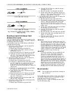
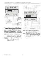
Fig. 18. Controller wiring diagram (CLLYUL6438S shown)
for typical AHU application
NOTE 1:
Earth ground wire length should be held to a
minimum. Use the heaviest gauge wire available,
up to 14 AWG (2.0 mm
2
), with a minimum of 18
AWG (1.0 mm
2
), for earth ground wire.
NOTE 2:
Analog outputs from sensor are 4…20 mA signals.
A 499
Ω
1% tolerance (or better) precision resistor
is required to drive this and other 4…20 mA signal
devices. Place this resistor as close as possible to
the driven device.


