Honeywell CentraLine LYNX LON CLLYUL1012S Product Data Download Page 16

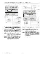
LYNX LON PROGRAMMABLE, VAV/UNITARY CONTROLLERS – PRODUCT DATA 

Manufactured for and on behalf of the Environmental and Combustion Controls Division of Honeywell Technologies Sàrl, Rolle, Z.A. La Pièce 16, Switzerland by its Authorized Representative:


CentraLine 
Honeywell GmbH 
Böblinger Strasse 17 
71101 Schönaich, Germany 
Phone  +49 (0) 7031 637 845 
Fax 

+49 (0) 7031 637 740 

[email protected]


www.centraline.com 


Subject to change without notice 
EN0Z-0957GE51 R0615 


Controller Replacement (CLLYVL0000AS, 

CLLYVL4022AS, and CLLYVL6436AS) 

In the case of the CLLYVL0000AS, CLLYVL4022AS, and 
CLLYVL6436AS controllers (which are hard-wired to an 
actuator), perform the following actions to replace the com-
plete assembly (controller and actuator): 
1)  Remove all power from the controller. 
2)  Remove the two air flow pickup connections from the 

pressure sensor. 

3)  Remove the terminal blocks (see section “Terminal Block 

Removal”). 

4)  Remove the old controller and actuator assembly from its 

mounting. 
a)  Loosen the two bolts on the actuator clamp to 

release the actuator from the shaft. 

b)  Remove the controller's mounting screws. 
c)  Gently pull the controller and actuator assembly 

straight out, until the assembly is clear of the 
actuator shaft. 

5)  Mount the new controller and actuator assembly (see 

section “Installation” on page 2). 

6)  Reconnect the two air flow pickup tubes to the pressure 

sensor (see section “Piping (CLLYVL0000AS, 
CLLYVL4022AS, and CLLYVL6436AS, 
CLLYVL6438NS)” on page 6). 

7)  Replace the terminal blocks: 

a)  Insert each terminal block onto its alignment pins. 
b)  Press straight down to firmly seat it. 
c)  Repeat for each terminal block. 

8)  Restore power to the controller. 
9)  Perform procedure described in section “Checkout” on 

page 14. 


Controller Replacement (CLLYVL6438NS) 

To replace the CLLYVL6438NS, proceed as follows: 
1)  Remove all power from the controller. 
2)  Remove the two air flow pickup connections from the 

pressure sensor. 

3)  Remove the terminal blocks (see section “Terminal Block 

Removal”). 

4)  Remove the old controller from its mounting. 
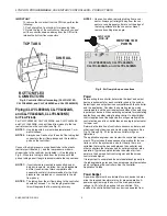
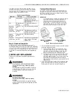
 

IMPORTANT 
(IN THE CASE OF CONTROLLERS MOUNTED TO A DIN 
RAIL): 

1)  Push straight up from the bottom to release the top 

pins. 

2)  Rotate the top of the controller outwards to release the 

bottom flex connectors (see Fig. 8). 


5)  Mount the new controller (see section “Installation” on 

page 2). 

6)  Reconnect the two air flow pickup tubes to the pressure 

sensor (see section “Piping (CLLYVL0000AS, 
CLLYVL4022AS, and CLLYVL6436AS, 
CLLYVL6438NS)” on page 6). 

7)  Replace the terminal blocks: 

a)  Insert each terminal block onto its alignment pins. 
b)  Press straight down to firmly seat it. 
c)  Repeat for each terminal block. 

8)  Restore power to the controller. 
9)  Perform procedure described in section “Checkout” on 

page 14. 


Controller Replacement (CLLYUL1012S, 

CLLYUL4024S, and CLLYUL6438S) 

To replace the CLLYUL1012S, CLLYUL4024S, and 
CLLYUL6438S controller, proceed as follows: 
1)  Remove all power from the controller. 
2)  Remove the terminal blocks (see section “Terminal Block 

Removal”). 

3)  Remove the old controller from its mounting. 
 

IMPORTANT 
(IN THE CASE OF CONTROLLERS MOUNTED TO A DIN 
RAIL): 

1)  Push straight up from the bottom to release the top 

pins. 

2)  Rotate the top of the controller outwards to release 

the bottom flex connectors (see Fig. 8). 

 
4)  Mount the new controller (see section “Installation” on 

page 2). 

5)  Replace the terminal blocks: 

a)  Insert each terminal block onto its alignment pins. 
b)  Press straight down to firmly seat it. 
c)  Repeat for each terminal block. 

6)  Restore power to the controller. 
7)  Perform procedure described in section “Checkout” on 

page 14. 

 
L

ON

W

ORKS

®, L

ON

T

ALK

®, and N

EURON

® are registered 

trademarks of Echelon® Corporation. 
L

ON

M

ARK

® and the LonMark logo are trademarks of the 

LonMark Association. 
N

IAGARA 

F

RAMEWORK

® and the Niagara framework logo are 

registered trademarks of Tridium, Inc. 
 

Summary of Contents for CentraLine LYNX LON CLLYUL1012S

Page 1: ...roller for LONWORKS network communications Each controller has flexible uni versal inputs for external sensors digital inputs and a mix of analog and digital triac outputs see Table 1 The accom panying image is of the model CLLYVL6436AS which includes an actuator Table 1 Controller configurations model type Universal Inputs UI Digital Inputs DI Analog Out puts AO Digital Out puts DO velocity press...

Page 2: ... TRIAC OUTPUT DO CIRCUITS Voltage rating 20 30 VAC at 50 60 Hz Current rating 25 500 mA continuous and 800 mA AC rms for 60 ms ANALOG OUTPUT AO CIRCUIT Configuration for current voltage All 3 analog outputs can be individually configured for current or voltage Configuration as digital outputs FALSE 0 0 Vdc 0 mA TRUE 100 max 11 Vdc 22 mA Analog current outputs Current output range 4 20 mA Output lo...

Page 3: ...rotation Adjust the two set screws closer together to reduce the rotation travel Each hash mark indicator on the bracket represents approximately 6 5 of rotation per side NOTE 2 The DECLUTCH button when pressed allows you to rotate the universal shaft adapter see Fig 1 UNIVERSAL SHAFT CLAMPING BOLTS 2 UNIVERSAL SHAFT ADAPTER MECHANICAL END LIMIT SET SCREWS 2 DECLUTCH BUTTON Fig 1 Floating actuator...

Page 4: ...8 10 Nm torque When the actuator closes the damper rotates CW 90 to fully close 4 If the damper rotates CCW to open and the angle of the damper open to closed is 45 or 60 a Manually open the damper fully rotate CCW b The actuator is shipped with the mechanical end limits set at 95 Adjust the two mechanical end limit set screws to provide the desired amount of rotation Adjust the two set screws clo...

Page 5: ...on cover 1 2 3 4 5 6 7 8 9 0 1 2 3 4 5 6 7 8 9 0 2 2 2 2 2 2 2 2 2 2 3 3 3 3 3 3 3 3 3 4 1 2 3 4 5 6 7 8 9 0 1 2 3 4 5 6 7 8 9 0 2 2 2 2 2 2 2 2 2 2 3 3 3 3 3 3 3 3 3 4 1 2 3 4 5 6 7 8 1 2 3 4 5 6 7 8 1 1 1 1 1 1 1 1 1 2 3 4 5 6 7 0 9 1 1 1 1 1 1 1 1 1 2 3 4 5 6 7 0 9 146139 139 128 128 164 164 174 CLLYUL6438S CLLYVL6438NS DEPTH 57 DEPTH 57 Fig 7 Panel mounting dimensions in mm CLLYVL6438NS and CL...

Page 6: ...ters to cut the edge of the tubing attached to the connector Never remove by pulling at an angle 1 2 3 4 5 6 7 8 9 0 1 2 2 2 2 2 2 2 2 2 2 3 CLLYVL0000AS CLLYVL4022AS CLLYVL6436AS and CLLYVL6438NS P AIR FLOW PICK UP RESTRICTOR PORTS Fig 9 Air flow pick up connections Power Before wiring the controller determine the input and output device requirements for each controller used in the system Select ...

Page 7: ...ground connection terminal 3 wire run as short as possible NOTE 4 Do not connect the universal input COM terminals analog output COM terminals or the digital input output COM terminals to earth ground See Fig 15 through Fig 20 for wiring examples The 24 VAC power from an energy limited Class II power source must be provided to the controller To conform to Class II restrictions U S only the transfo...

Page 8: ...o the LONWORKS Bus Jack see also Fig 13 IMPORTANT All field wiring must conform to local codes and ordinances or as specified on installation drawings IMPORTANT Do not bundle device output wires with sensor digital input or communications LONWORKS Bus wires IMPORTANT Do not use different wire types or gauges on the same LONWORKS Bus segment The step change in line impedance characteristics causes ...

Page 9: ...OMMUNICATIONS DIGITAL OUTPUTS 9 DO 1 DIGITAL OUTPUT 10 DO 2 DIGITAL OUTPUT 11 COM COMMON 12 DO 3 DIGITAL OUTPUT 13 DO 4 DIGITAL OUTPUT 14 COM COMMON 15 DO 5 DIGITAL OUTPUT 16 DO 6 DIGITAL OUTPUT 17 COM COMMON 18 a DO 7 DIGITAL OUTPUT 19 a DO 8 DIGITAL OUTPUT 20 a COM COMMON ANALOG OUTPUTS b 21 AO 1 ANALOG OUTPUT 22 COM COMMON 23 AO 2 ANALOG OUTPUT 24 AO 3 ANALOG OUTPUT 25 COM COMMON DIGITAL INPUTS...

Page 10: ...controller s current operating mode see Fig 13 and Fig 14 CAUTION Electrical Damage Hazard Can cause controller damage or failure Do not use any metal object to press the NEURON Service Pin Use instead a plastic rod or wooden implement such as a pencil with the lead broken off to press the pin Using a metal object can damage the controller s circuitry LonWorks Bus Convenience Jack The LONWORKS Bus...

Page 11: ...INDOW CLOSED OCCUPANCY SENSOR CONTACTS CLOSED OCCUPIED 2 Fig 15 Controller wiring diagram CLLYVL6438NS shown for typical VAV application NOTE 1 Earth ground wire length should be held to a minimum Use the heaviest gauge wire available up to 14 AWG 2 0 mm2 with a minimum of 18 AWG 1 0 mm 2 for earth ground wire NOTE 2 Contacts must be suitable for dry switching 5 V at 10 mA Use sealed type gold fla...

Page 12: ...rth ground wire length should be held to a minimum Use the heaviest gauge wire available up to 14 AWG 2 0 mm2 with a minimum of 18 AWG 1 0 mm2 for earth ground wire NOTE 2 Turn power OFF before setting the DIP switches NOTE 3 Ensure that all transformer power wiring is as shown Reversing terminations will result in equipment malfunction 1 2 3 4 5 6 7 8 9 0 1 2 3 4 5 6 7 8 9 0 2 2 2 2 2 2 2 2 2 2 3...

Page 13: ... 499 Ω 1 tolerance or better precision resistor is required to drive this and other 4 20 mA signal devices Place this resistor as close as possible to the driven device 1 2 3 4 5 6 7 8 9 0 1 2 3 4 5 6 7 8 9 0 2 2 2 2 2 2 2 2 2 2 3 3 3 3 3 3 3 3 3 4 1 2 3 4 5 6 7 8 1 1 1 1 1 1 1 1 1 1 2 1 2 3 4 5 6 7 8 9 0 0 9 CLLYUL6438S 24 VAC 24 VAC COM E GND SHLD SBUS1 SBUS2 NET 1 NET 2 DO 1 DO 2 COM COM COM CO...

Page 14: ...common terminals for high side switching NOTE All wiring must comply with applicable electrical codes and ordinances or as specified on installation wiring diagrams For guidelines for wiring run lengths and power budget see section Power on page 6 Verify Termination Module Placement Multiple Controllers Only The installation wiring diagrams should indicate the locations for 209541B termination mod...

Page 15: ...r electrical characteristics of this device in any way If trouble shooting indicates a malfunction replace the controller WARNING Electrical Shock Hazard Can cause severe injury death or property damage To prevent electrical shock or equipment damage disconnect power supply before beginning controller replacement Terminal Block Removal To simplify controller replacement all terminal blocks are des...

Page 16: ...follows 1 Remove all power from the controller 2 Remove the two air flow pickup connections from the pressure sensor 3 Remove the terminal blocks see section Terminal Block Removal 4 Remove the old controller from its mounting IMPORTANT IN THE CASE OF CONTROLLERS MOUNTED TO A DIN RAIL 1 Push straight up from the bottom to release the top pins 2 Rotate the top of the controller outwards to release ...

Reviews: