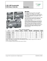


LYNX LON PROGRAMMABLE, VAV/UNITARY CONTROLLERS – PRODUCT DATA
EN0Z-0957GE51 R0615
2
TECHNICAL DATA
GENERAL SPECIFICATIONS
Rated voltage:
20 … 30 VAC; 50/60 Hz
Power consumption:
100 VA for controller and all connected
loads (incl. actuator on CLLYVL0000AS,
CLLYVL4022AS, and CLLYVL6436AS)
Controller-only load:
5 VA max. (CLLYUL1012S,
CLLYUL4024S, and CLLYUL6438S and
CLLYVL6438NS)
Cont actuator load: 9 VA max. (CLLYVL0000AS,
CLLYVL4022AS, and CLLYVL6436AS)
External sensors power
output:
20 Vdc ± 10% at 75 mA, max.
VAV OPERATING & STORAGE TEMPERATURE AMBIENT RATING
CLLYVL0000AS,
CLLYVL4022AS,
CLLYVL6436AS,
CLLYVL4024NS, and
CLLYVL6438NS:
0 … +50 °C
CLLYUL1012S,
CLLYUL4024S, and
CLLYUL6438S:
-40 … +65.5 °C
Relative humidity:
5 … 95%, non-condensing
LED:
Provides status for normal operation, con-
troller download process, alarms, manual
mode, and error conditions
VELOCITY PRESSURE SENSOR (CLLYVL0000AS,
CLLYVL4022AS, CLLYVL6436AS & CLLYVL6438NS, ONLY)
Operating range:
0 … 374 Pa
FLOATING ACTUATOR (CLLYVL0000AS, CLLYVL4022AS, AND
CLLYVL6436AS)
Rotation stroke:
95° ± 3° for CW/CCW-opening dampers
Torque rating:
5 Nm
Runtime for 90° rotation:
90 sec at 60 Hz
Operating temperature:
-20 … +60 °C
REAL-TIME CLOCK
Operating range:
24-hr, 365-day, multi-year calendar, incl.
day of week and configuration for auto-
matic daylight savings time adjustment to
occur at 2:00 a.m. local times on
configured start and stop dates
Power failure back-up:
24 hrs at 0 … +38 °C,
22 hrs at 38 … 50 °C
Accuracy:
±1 minute per month at 25 °C
DIGITAL INPUT (DI) CIRCUITS
Voltage rating:
0 … 30 Vdc open circuit
Input type:
Dry contact to detect open / closed circuit
Operating range:
Open circuit = FALSE,
closed circuit = TRUE
Resistance:
Open circuit > 3k
Ω
,
closed circuit < 500
Ω
DIGITAL TRIAC OUTPUT (DO) CIRCUITS
Voltage rating:
20 … 30 VAC at 50/60 Hz
Current rating:
25 … 500 mA continuous, and 800 mA
(AC rms) for 60 ms.
ANALOG OUTPUT (AO) CIRCUIT
Configuration for current /
voltage:
All 3 analog outputs can be individually
configured for current or voltage.
Configuration as digital
outputs:
FALSE (0%) -> 0 Vdc (0 mA)
TRUE (100%) -> max., 11 Vdc (22 mA)
Analog current outputs
Current output range:
4 … 20 mA
Output load resistance:
550
Ω
, max.
Analog voltage outputs
Voltage output range:
0 … 10 Vdc
Max. output current:
10.0 mA
UNIVERSAL INPUT (UI) CIRCUITS
See
Table
2
for UI circuit specifications.
Table 2. Universal input circuit specifications
input type
sensor type
operating range
room/zone discharge air
outdoor air temperature
20k
Ω
NTC -40 … +93 °C
resistive input
generic
100 … 100k
Ω
voltage input
transducer,
controller
0 … 10 Vdc
discrete input
dry contact
closure
open circuit > 3k
Ω
;
closed circuit < 3k
Ω
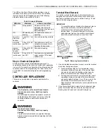
BEFORE INSTALLATION
The controller is available in eight models (see Table 1).
Before installing the controller, review the power, input, and
output specifications in section “Technical Data”.
Hardware driven by Triac outputs must have a min.
current draw, when energized, of 25 mA and a max.
current draw of 500 mA.
Hardware driven by the analog current outputs must have
a max. resistance of 550
Ω
, resulting in a max. voltage of
11 V when driven at 20 mA. If resistance exceeds 550
Ω
,
voltages up to 18 Vdc are possible at the analog output
terminal.
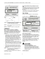
WARNING
Electrical Shock Hazard.
Can cause severe injury, death or property
damage.
To prevent electrical shock or equipment damage,
disconnect power supply before beginning wiring or
making wiring connections.
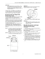
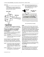
INSTALLATION
The controller must be mounted in a position that allows
clearance for wiring, servicing, removal, connection of the
L
ON
W
ORKS
® Bus Jack and access to the Neuron® Service
Pin (see Fig. 13).
The controller may be mounted in any orientation.