


LYNX LON PROGRAMMABLE, VAV/UNITARY CONTROLLERS – PRODUCT DATA
EN0Z-0957GE51
R0615
11
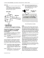
Typical controller wiring for PWM reheat and PWM
peripheral heat valve actuator (see Fig. 17).
Typical controller wiring for AHU application (see Fig. 18).
Typical controller wiring for 4…20 mA enthalpy sensors
and digital inputs (see Fig. 19).
Typical controller wiring for 4…20 mA heating, cooling,
and model ML6161 floating motor control (see Fig. 20).
Typical controller wiring for a pneumatic transducer, model
RP7517B (see Fig. 21).
1 2 3 4 5 6 7 8 9 0 1 2 3 4 5 6 7 8 9 0
2 2 2 2 2 2 2 2 2 2 3 3 3 3 3 3 3 3 3 4
1 2 3 4 5 6 7 8
1
1 1 1 1 1 1 1 1 1 2
1
2 3 4 5 6 7 8 9 0
0
9
CLLYVL6438NS
24 V
A
C
24 V
A
C COM
E G
N
D
SH
L
D
SB
U
S
1
SB
U
S
2
NE
T-
1
NE
T-
2
DO
-1
DO
-2
CO
M
CO
M
CO
M
CO
M
DO
-3
DO
-4
DO
-5
DO
-6
DO
-7
DO
-8
AO
-1
AO
-2
AO
-3
DI
-1
DI
-2
DI
-3
DI
-4
20VD
C
UI
-1
UI
-2
UI
-3
UI
-4
UI
-5
UI
-6
CO
M
CO
M
CO
M
CO
M
CO
M
CO
M
1
24
V
A
C
24V
AC
C
O
M
Lo
nW
o
rk
s Bu
s
Lo
nW
o
rk
s Bu
s
CLCM4T111
WALL MODULE
GND
SENSOR
SET-POINT
BYPASS
LED
5
6
7
4
3
2
1
AIR FLOW
PICK-UP
C770A AIR
TEMP. SENSOR
REHEAT STAGE 3
REHEAT STAGE 2 (OR CLOSE)
REHEAT STAGE 1 (OR OPEN)
DAMPER CLOSE
DAMPER OPEN
SERIES OR PARALLEL
FAN CONTACTOR
REHEAT STAGE
CONTACTORS
ML6161
DAMPER
ACTUATOR
CCW
COM
CW
WINDOW CONTACTS
(CONTACTS CLOSED
= WINDOW CLOSED)
OCCUPANCY SENSOR
(CONTACTS CLOSED
= OCCUPIED)
2
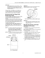
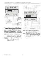
Fig. 15. Controller wiring diagram (CLLYVL6438NS
shown) for typical VAV application
NOTE 1:
Earth ground wire length should be held to a
minimum. Use the heaviest gauge wire available,
up to 14 AWG (2.0 mm
2
), with a minimum of 18
AWG (1.0 mm
2
), for earth ground wire.
NOTE 2:
Contacts must be suitable for dry switching, 5 V at
10 mA. Use sealed type, gold-flashed, or pimpled
contacts.
1 2 3 4 5 6 7 8 9 0 1 2 3 4 5 6 7 8 9 0
2 2 2 2 2 2 2 2 2 2 3 3 3 3 3 3 3 3 3 4
1 2 3 4 5 6 7 8
1
1 1 1 1 1 1 1 1 1 2
1
2 3 4 5 6 7 8 9 0
0
9
CLLYVL6436AS
24 V
A
C
24 V
AC C
O
M
E G
N
D
SH
L
D
SB
U
S
1
SB
U
S
2
NE
T-
1
NE
T-
2
DO
-1
DO
-2
CO
M
CO
M
CO
M
DO
-3
DO
-4
DO
-5
DO
-6
AO
-1
AO
-2
AO
-3
DI
-1
DI
-2
DI
-3
DI
-4
20VD
C
UI
-1
UI
-2
UI
-3
UI
-4
UI-5
UI
-6
CO
M
CO
M
CO
M
CO
M
CO
M
CO
M
STAGE 3
STAGE 2
STAGE 1
AIR FLOW
PICK-UP
CLCM4T111
WALL MODULE
GND
SENSOR
SET-POINT
BYPASS
LED
5
6
7
4
3
2
1
WINDOW CONTACTS
(CONTACTS CLOSED
= WINDOW CLOSED)
OCCUPANCY SENSOR
(CONTACTS CLOSED
= OCCUPIED)
2
C770A AIR
TEMP. SENSOR
1
24
V
A
C
2
4V
A
C CO
M
Lon
W
o
rk
s B
u
s
Lon
W
o
rk
s B
u
s
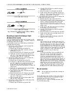
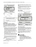
Fig. 16. Controller wiring diagram (CLLYVL6436AS
shown) for typical VAV application with staged reheat
NOTE 1:
Earth ground wire length should be held to a
minimum. Use the heaviest gauge wire available,
up to 14 AWG (2.0 mm
2
), with a minimum of 18
AWG (1.0 mm
2
), for earth ground wire.
NOTE 2:
Contacts must be suitable for dry switching, 5 V at
10 mA. Use sealed type, gold-flashed, or pimpled
contacts.


