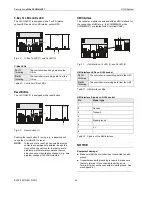
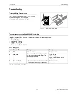
background image

Troubleshooting 

LION System 

EN1Z-0921GE51 R0315 


42

C-Bus Tx and Rx LEDs 

case 

C-Bus LEDs 

Meaning 

Remedy 


Both LEDs are flashing 

If the C-bus is functioning properly, then the 
CLLIONLC01 Controller is functioning properly

No action necessary 

If the C-bus is not functioning properly, then 
the termination can be wrong 


Check C-bus termination switch S1 
(location: see Fig. 45 on page 32) 

Both LEDs are OFF 

No C-bus communication 


Check C-bus settings 

Both LEDs are flashing 
synchronously 

No C-bus communication 


Check C-bus wiring 

Table 45  CLLIONLC01 C-Bus Tx and Rx LEDs 


HMI Tx and Rx LEDs 

case 

HMI LEDs 

Meaning 

Remedy 

Both LEDs are flashing 

If the HMI Interface is functioning properly, 
then the CLLIONLC01 Controller is functioning 
properly 

No action necessary 

Both LEDs are OFF 

No HMI Interface communication 


Check HMI Interface connection and 
proper earthing of connected 
hardware 

Table 46  CLLIONLC01 HMI Tx and Rx LEDs 


Modem Tx and Rx LEDs 

case 

Modem LEDs 

Meaning 

Remedy 

Both LEDs are flashing 

If the Modem Interface is functioning properly, 
then the CLLIONLC01 Controller is functioning 
properly 

No action necessary 

Both LEDs are OFF 

No Modem Interface communication 


Check Modem Interface connection 

Table 47  CLLIONLC01 modem Tx and Rx LEDs 


Summary of Contents for Centraline LION

Page 1: ...Terminals 22 Connecting Power Supply 23 Connecting Single Bus Controller Systems 24 Connecting Panel Bus and LONWORKS Bus Mixed Controller Systems 25 Setting Address of Panel Bus I O Modules 27 Setting I O Bus Switch 27 Connecting Field Devices 28 Commissioning I O Modules 29 Updating Software 29 Connecting to External Systems or Interfaces 30 Connecting via LONWORKS Bus 30 Connecting via C Bus 31...

Page 2: ...orage temperatures to evaporate The LION System must be installed in such a manner e g in a lockable cabinet as to ensure that uncertified persons have no access to the terminals Investigated according to United States Standard UL916 USL listed Investigated according to Canadian National Standard s C22 2 CNL listed Safety Information as per EN60730 1 Purpose The LION System is an incorporated elec...

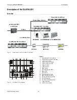
Page 3: ...ler provides interface connections which allow connection to external systems Auxiliary parts enable special features Panel Bus 40 m CLLIONLC01 CLIOxx CLMMI00N22 or CLMMI00N31 MODEM LonWorks Bus XFCLxxx XFCxxx SERVAL LonWorks I O CLIOLxx Panel I O CLIOPxx C Bus existing XL500 controllers Fig 1 LION System architecture Controller I O Modules Fig 2 CLLIONLC01 Controller and I O modules ...

Page 4: ...distinguish modules and components the following color coding is used Color Part Red All user accessible adjustable mechanical parts i e bridge connectors and locking mechanism and operating controls manual overrides etc Light gray Panel Bus I O modules exc CLIOP831A Black CLIOP831A mixed Panel Bus I O module Dark gray LONWORKS Bus I O modules Table 2 Color coding of LION Modules CLLIONLC01 MIXED ...

Page 5: ...rity Override Indicating Units Specifically the positions of the manual override switches and potentiometers directly control the outputs independently of the LION Controller and HMI When a manual override switch or potentiometer is not in its default position auto the cor responding output LED will blink continuously and the output module will send a feedback signal with the status manual overrid...

Page 6: ...ush in terminals for distributing signals power XS831 A1 B1 A2 B2 A3 B3 A4 B4 G1 G2 A5 B5 A6 B6 A7 B7 A8 B8 Two groups of four pairs of push in terminals for converting 0 20 mA signals into 0 10 Vdc signals and one push in ground terminal per group Table 5 Auxiliary parts Spare Parts Module Type Figure Corresponding I O modules CLIOP CLIOL Information Cross connectors red XS815 824 825 Connects 6 ...

Page 7: ... mm 2 Overvoltage protection All inputs and outputs are protected against 24 VAC and 40 VDC overvoltage as well as against short circuiting Calculated lifetime of weakest component under typical operating conditions MTBF 13 7 years Table 7 System data Standards Protection class IP20 Product standard EMC EN 60730 1 EN 60730 2 9 Testing electrical components IEC68 Certification CE System transformer...

Page 8: ...ada NEC Class 2 transformers must be used Current Requirement When selecting the appropriate transformer take into account the number of individual modules accessories and field devices in determining the total current requirement Devices powered Current requirement 24 VAC 24 VDC CLLIONLC01 with CLMMI00N22 backlight ON and with watchdog load max 500 mA 690 mA 640 mA CLLIONLC01 with CLMMI00N22 back...

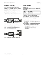
Page 9: ...nnection examples on page 28 Fusing Specifications Please observe the following when selecting fusing F1 F2 for the CLLIONLC01 I O modules and active field devices Use separate fusing for different loads e g for the CLLIONLC01 and I O modules on one hand versus for active field devices on the other Fuse ratings must always be calculated according to the loads connected Refer to the load tables app...

Page 10: ...ng NOTE Star connection is not allowed as this might cause uncontrollable line reflections Instead of LION Controllers other C Bus controllers e g the Excel 500 Excel 100 PANTHER can also be connected LION Excel 100 Excel 500 PANTHER Fig 4 C Bus topology Excel 5000 Accessories Besides the auxiliary parts of Table 5 on page 6 the following accessories are available Preconfigured Connection Cables T...

Page 11: ...ails XW586 Cable Details 1 5 4 3 2 9 8 7 6 1 2 3 6 7 8 4 5 RS232 plug sub D male DCD DSR RxD RTS TxD CTS DTR GND XW586 RJ45 plug with clip at front 5V Fig 10 XW586 cable details LONWORKS Bus Termination Modules Type Description XAL Term2 LONWORKS connection and ter mination module which can be mounted on DIN rails and in fuse boxes Table 15 LONWORKS Bus termination modules Cable Specifications Pow...

Page 12: ...n 8471 400 m 1300 ft 500 m 1650 ft Level IV 22AWG 400 m 1300 ft 500 m 1650 ft JY St Y 2 x 2 x 0 8 320 m 1050 ft 500 m 1650 ft TIA568A Cat 5 24AWG twisted pair 250 m 825 ft 450 m 1500 ft Table 19 Free topology singly terminated specifications NOTICE Unpredictable reflections on the bus due to step change in line impedance characteristics Do not use different wire types or gauges on the same LONWORK...

Page 13: ... cabinet A Y ST Y 2 x 2 x 0 8 shielded twisted pair Europe outside cabinet AK 3702 unshielded twisted pair US not approved for Europe AK 3740A shielded US low cost not approved for Europe Belden 9842 twisted pair Europe US also possible Belden 9841 shielded US AK 3702 unshielded twisted pair US not approved for Europe AK 3740A shielded US low cost not approved for Europe Table 21 C Bus cable types...

Page 14: ...1 Controller module outside dimensions in mm Pluggable I O Modules LOCK 89 5 94 1 51 5 45 83 67 5 14 110 XS814 Aux Terminal Package optional 28 30 6 SWIVEL LABEL HOLDER 38 SCREW TYPE TERMINALS Fig 12 Pluggable I O modules shown with manual overrides including XS814 Aux Terminal Package dimensions in mm ...

Page 15: ...18 19 20 DI Binary Inputs Analog Inputs Analog Outputs 24V Relays GND S2 DO Install Instr EN1B 0375GE51 CLIOP830A 12 BI 8 AI 8 AO 6 RO 24V 15VA T50 0706AX0001 XFU830A Made in Germany 0532 8 2 1 0 F E DCB 9 8 7 6 5 4 3 A 40 External 24V for relay 1 5 24V J1 J2 J3 J4 J5 71 75 76 77 78 COM a COM b 24V 24V 0 COM a COM b 24V 24V 0 72 73 74 A1 A2 A3 A4 A5 A6 A7 A8 A9 B1 B2 B3 B4 B5 B6 B7 B8 B9 A A1 A2 A...

Page 16: ...7 ABCDFERTAQWESDERT7 8 ABCDFERTAQWESDERT8 1 ABCDFERTAQWESDERT1 2 ABCDFERTAQWESDERT2 3 ABCDFERTAQWESDERT3 4 ABCDFERTAQWESDERT4 5 ABCDFERTAQWESDERT5 6 ABCDFERTAQWESDERT6 7 ABCDFERTAQWESDERT7 8 ABCDFERTAQWESDERT8 1 2 3 4 5 6 7 8 21 9 GND GND AI AO VAUX 10 11 12 13 14 15 16 17 18 25 26 22 1 2 3 4 5 6 7 8 GND BI 13 14 15 16 17 18 19 20 21 22 23 24 25 26 1 2 3 4 5 6 7 8 9 10 11 12 1 2 3 4 5 6 7 8 9 10 1...

Page 17: ...d electrically with bridge connectors Controller and terminal sockets on different DIN rails must be connected using cables see Fig 14 and page 23 NOTICE Risk of malfunction Wire Panel Bus I O modules and LONWORKS Bus I O modules separately When using both Panel Bus and LONWORKS Bus I O modules in a LION System LONWORKS Bus I O modules must be connected to the controller via LON terminals 11 14 Po...

Page 18: ...then be swung away from the rail Fig 20 Releasing latch Mounting Dismounting Electronic Modules Mounting Electronic Modules NOTE Electronic modules can be removed from the socket or inserted into the sockets without switching off the power supply but the resultant behavior of connected field devices must be taken into consideration Make sure that terminal socket und electronic I O module match see...

Page 19: ...Modules are mounted on the terminal socket appropriate for the elec tronic module see Table 4 on page 5 The electronic module is mounted onto the manual disconnect module WARNING Risk of electric shock or equipment damage The XS812RO Manual Disconnect Module is designed for 24 V applications only Never use the XS812RO Manual Disconnect Module with line voltage Mounting Manual Disconnect Modules Ma...

Page 20: ...ry Terminal Packages are suitable for mixed I O modules only Specifically they can be mounted on the top and or bottom of the CLIOP830A For reasons of mechanical stability a max of two rows of Auxiliary Terminal Packages may be mounted together on the CLIOP830A Mounting Auxiliary Terminal Packages Push the auxiliary terminal package onto the grooves of the corresponding terminal socket the mixed I...

Page 21: ...to the right and to left until the cross connector is released If desired insert another cross connector Fig 28 Dismounting the cross connectors Mounting Dismounting Swivel Label Holders NOTE A swivel label holder is included in the delivery of each module Use only the short long swivel label holders appropriate for the given type pluggable or mixed respectively of I O module Mounting Swivel Label...

Page 22: ...l screws thus preventing the accidental touching of live parts Observe precautions for handling electrostatic sensitive devices Wiring Push in Terminals The terminal sockets of the pluggable I O modules are available in versions XS821 22 XS823 and XS824 25 featuring convenient push in terminals for easy wiring The CLIOP830A likewise features push in terminals For correct wiring cables must fulfill...

Page 23: ...t the transformer to terminals 1 and 2 of the CLLIONLC01 Controller I O I O I O CPU 2 1 B A A 3 m AND B 3 m Fig 30 Wiring power supply from the first transformer to the controller module Additional Transformer Connect the additional transformer in a second room or cabinet to terminals 73 and 74 or 77 and 78 of an I O module I O I O 71 72 73 74 MAX 3 m TRANS FORMER 2 Fig 31 Wiring the power supply ...

Page 24: ...I O 75 75 71 71 71 71 76 76 72 72 72 72 77 77 73 73 73 73 78 78 74 74 74 74 CPU 1 2 Fig 32 Wiring the power supply and the communication lines to the I O modules Max Power Cable Length The max length for power supply cable per side is 3 m This includes the connection cables between the rails the lengths of the modules and the cable from the transformer Panel Bus I O Modules in Separate Rooms In th...

Page 25: ...onnecting I O Modules with Each Other For connecting the I O modules with each other proceed as described for single bus controller systems on page 23 Connecting I O Modules to the Controller Panel Bus I O Modules Connect communication terminals 71 72 or 75 76 of Panel Bus I O modules to communication terminals 71 74 or 75 78 of the controller module using either Bridge connectors for flush mounti...

Page 26: ...s 73 71 72 74 77 75 76 78 73 71 72 74 77 75 76 78 73 71 72 74 77 75 76 78 73 71 72 74 77 75 76 78 73 71 72 74 77 75 76 78 73 71 72 74 77 75 76 78 Fig 35 Mixed bus system correct wiring 73 71 72 74 77 75 76 78 73 71 72 13 11 14 12 3 1 4 2 74 77 75 76 78 73 71 72 74 77 75 76 78 73 71 72 74 77 75 76 78 Panel Bus I O modules LonWorks Bus modules 73 71 72 74 77 75 76 78 73 71 72 74 77 75 76 78 73 71 72...

Page 27: ... to set the address to the one already defined using the engineering tool LOCK 4 4 Fig 37 HEX switch location NOTE If the HEX switch is changed the Panel Bus I O module will revert to its default configuration NOTE With LONWORKS Bus I O modules the HEX switch is without function Setting I O Bus Switch Set the I O Bus switch S2 of the CLLIONLC01 depending on the modules connected to terminals 71 78...

Page 28: ... 10 Vdc 24 V0 24 V0 230 V 230 V 24 V 24 V max 400 m 822 1 2 1 8 GND Y 24V 11 18 F1 F2 CLLIONLC01 Fig 40 Power supply of field devices via a separate transformer Cabling Field Devices Cable Routing Route low voltage signal and output cables separately from mains cables Cable Min distance Shielded 10 mm 0 4 in Unshielded 100 mm 4 in Table 26 Min distances to power mains cables All low voltage signal...

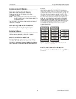
Page 29: ...When the controller firmware is updated from V3 01 03 to V3 02 02 if newer firmware is available for individual Panel Bus I O modules their firmware will be automatically up dated too In this example newer Panel Bus I O module firmware is indeed available for all but the CLIOP830A Mixed Panel Bus I O modules As a consequence the firm ware of all of the Panel Bus I O modules except for the CLIOP830...

Page 30: ... other controller systems to additional LONWORKS Bus I O modules or to laptops LONWORKS Bus Termination Depending upon the configuration either 1 or 2 termination modules are required for terminating a LONWORKS bus with FTT devices on it The following LONWORKS termination unit is available for this purpose XAL Term2 LONWORKS Connection and Termination Module which can be mounted on DIN rails and i...

Page 31: ...RKS interface of the CLLIONLC01 Connecting the CLMMI00N22 Operator Interface Connect the CLMMI00N22 Operator Interface to the HMI interface of the CLLIONLC01 by means of the XW882 cable or the XW582 cable connected with an XW586 cable For mounting details refer to the CLMMI00N22 Installation Instructions Product Literature no EN2B 0126GE51 For cable details refer to section Preconfigured Connectio...

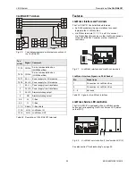
Page 32: ...ON C Bus in C Bus S1 S2 Modem I O Bus Rx Tx Power Alarm C Bus out C BUS PC HMI 13 3 96 14 4 10 7 12 2 85 9 6k all Panel LON mid end 76k 76k 11 1 3 1 2 4 5 6 7 8 9 11 12 13 10 14 15 16 17 18 1 2 Fig 45 CLLIONLC01 front details Legend 1 Power supply for I O modules 2 I O Bus communication terminals 3 LONWORKS interface 4 LONWORKS service button 5 LONWORKS service LED 6 C Bus Tx LED 7 C Bus Rx LED 8 ...

Page 33: ... 10 Shield C Bus shield 11 12 LON LONWORKS IN 13 14 LON LONWORKS OUT Table 28 Description of CLLIONLC01 terminals Features LONWORKS Interface and Terminals The CLLIONLC01 Controller Module features An RJ45 socket serving as an interface to connect laptops to the LONWORKS Bus LONWORKS terminals 11 12 13 and 14 to connect LONWORKS Bus I O modules or other LONWORKS devices to the CLLIONLC01 Controlle...

Page 34: ...end that you always save your application changes e g time program changes to FLASH memory HMI Interface The controller module is equipped with an HMI Interface for the connection of HMIs e g the CLMMI00N22 or the CLMMI00N31 or a laptop with XL Online CARE 3 12 45 78 8 Tx Rx 2 1 7 6 5 4 3 2 1 Fig 51 HMI interface Tx LED 1 and Rx LED 2 HMI interface LEDs on RJ45 socket Tx 1 flickering The controlle...

Page 35: ...oblem The controller performs a warm start If the problem persists the LED will become lit constantly see above See section Troubleshooting on page 39 Table 33 Controller alarm LED Power LED 2 green On Normal operation Flashing One or more of the internal voltage supplies are outside of the permissible ranges The controller stops operation Check wiring or see section Trouble shooting on page 39 Go...

Page 36: ...face Communication Speed Default setting 9600 baud The communication speed can be set to as high as 38 4 Kbaud e g using the CLMMI00N22 or CLMMI00N31 or a laptop with XL Online see Appendix 2 I O Bus Switch S2 The CLLIONLC01 features a 2 position I O Bus switch S2 I O Bus switch S2 must be set in accordance with the kind of I O modules connected to communication terminals 71 72 and 75 76 of the co...

Page 37: ...g 76k mid Up to 76800 baud without bus termination 76k end Up to 76800 baud with bus termination controller at the end of the C Bus Table 40 CLLIONLC01 C Bus termination switch S1 settings Memory Memory Size Usage SRAM 512 KB For controller application modem trend and firmware RACL application 128 KB Total application 192 KB Flash 2 MB Firmware 1 MB and application 1 MB storage EPROM 128 KB For bo...

Page 38: ...s I O modules Hex switch S2 Module addressing for Panel Bus I O modules LEDs located on the I O Module Feature Function Service LED yellow Service information see section Troubleshooting on page 39 Power LED green Information on power supply see section Troubleshooting on page 39 For detailed information on the features of the individual I O modules including a description of the software interfac...

Page 39: ...ubleshooting purposes Power LED green Alarm LED red LONWORKS service LED C Bus Tx and Rx LEDs HMI Tx and Rx LEDs Modem Interface Tx and Rx LEDs Power LED green case Power LED Meaning Remedy 1 ON Normal operation No action necessary 2 Flashing One or more of the internal voltage supplies are outside of the permissible ranges The controller stops operation Check power Check wiring If the problem per...
Page 40: ...hdog relay will be activated 22 minutes after power up without application Try powering down and then powering up the CLLIONLC01 If the problem persists check and if necessary reload the application If the problem still persists replace hardware 3 Flashing Although the controller has encountered a problem the watchdog alarm output has not yet been powered If the problem persists the LED will becom...

Page 41: ...ce hardware 3 Power up of controller Bad node hardware Replace hardware 4 Power up reset Node lacks application May be caused by neuron chip firmware when a mismatch occurs on application checksum Using EXCELON set module to configured online If the problem persists the MIP software on LW interface has been erased due to wrong setting performed using ECHELON tool Replace hardware 5 Anytime Watchdo...

Page 42: ...g Table 45 CLLIONLC01 C Bus Tx and Rx LEDs HMI Tx and Rx LEDs case HMI LEDs Meaning Remedy 1 Both LEDs are flashing If the HMI Interface is functioning properly then the CLLIONLC01 Controller is functioning properly No action necessary 2 Both LEDs are OFF No HMI Interface communication Check HMI Interface connection and proper earthing of connected hardware Table 46 CLLIONLC01 HMI Tx and Rx LEDs M...

Page 43: ...where in the plant The use of an earth leakage monitor is also possible to fulfill PELV if earth grounding is prohibited When is EN60204 1 Applicable to LION Systems Safety against electrical impact EN60204 1 is not mandatory this is because electrical safety is provided by the use of SELV and transformers according to standard EN60742 Safety against unexpected start up of rotating moving machines...

Page 44: ... Make sure that earth ground is connected to the correct terminal according to Fig 59 and the respective connection diagrams The XL40 XL50 XL100C Distributed IO Smart IO and the LION System can share one transformer The XC5010C Controller always requires its own transformer If EN60204 1 is applicable for the given type of controller the system ground has the same potential as one terminal of the p...

Page 45: ...mfaq in the search field Modem or ISDN Terminal Adapter Connection The modem interface of the CLLIONLC01 accepts a standard modem cable with a female 9 pin connector Fig 61 Modem interface Connect the cable that is supplied with the modem ISDN terminal adapter to the modem interface of the CLLIONLC01 Controller Modem Requirements A Frequently Asked Questions and Troubleshooting document is availab...

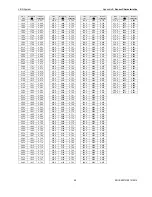
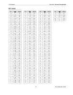
Page 46: ...512 0 201 30 0 514 0 202 31 0 516 0 203 32 0 518 0 204 33 0 520 0 205 34 0 522 0 205 35 0 524 0 206 36 0 527 0 207 37 0 529 0 208 38 0 531 0 209 39 0 533 0 210 40 0 535 0 210 41 0 537 0 211 42 0 539 0 212 43 0 542 0 213 44 0 544 0 214 45 0 546 0 215 46 0 548 0 215 47 0 550 0 216 48 0 553 0 217 49 0 555 0 218 Temp C Resistance Terminal voltage V 50 0 557 0 219 51 0 559 0 220 52 0 561 0 220 53 0 564...

Page 47: ... 7 60 2 27 48 0 7 29 2 20 49 0 7 00 2 14 50 0 6 72 2 07 51 0 6 45 2 01 52 0 6 19 1 94 53 0 5 95 1 88 54 0 5 72 1 82 55 0 5 49 1 77 56 0 5 28 1 71 57 0 5 08 1 66 58 0 4 88 1 61 59 0 4 69 1 56 Temp C Resistance k Terminal voltage V 60 0 4 52 1 51 61 0 4 35 1 46 62 0 4 18 1 41 63 0 4 03 1 37 64 0 3 88 1 32 65 0 3 73 1 28 66 0 3 59 1 24 67 0 3 46 1 20 68 0 3 34 1 16 69 0 3 21 1 13 70 0 3 10 1 09 71 0 ...

Page 48: ... 1255 0 480 67 0 1259 0 481 68 0 1263 0 483 69 0 1267 0 484 Temp C Resistance Terminal voltage V 70 0 1271 0 486 71 0 1275 0 487 72 0 1278 0 488 73 0 1282 0 490 74 0 1286 0 491 75 0 1290 0 493 76 0 1294 0 494 77 0 1297 0 495 78 0 1301 0 497 79 0 1305 0 498 80 0 1309 0 499 81 0 1313 0 501 82 0 1317 0 502 83 0 1320 0 503 84 0 1324 0 505 85 0 1328 0 506 86 0 1332 0 508 87 0 1336 0 509 88 0 1339 0 510...

Page 49: ...4 0 769 288 0 2077 0 770 289 0 2081 0 771 290 0 2085 0 773 291 0 2088 0 774 292 0 2092 0 775 293 0 2095 0 776 294 0 2099 0 777 295 0 2102 0 778 296 0 2106 0 780 297 0 2110 0 781 298 0 2113 0 782 299 0 2117 0 784 300 0 2120 0 785 301 0 2124 0 786 302 0 2127 0 787 303 0 2131 0 788 304 0 2134 0 789 305 0 2138 0 791 306 0 2142 0 792 307 0 2145 0 793 308 0 2149 0 794 309 0 2152 0 796 Temp C Resistance ...

Page 50: ...60 44 1205 3 0 462 45 1210 2 0 463 46 1215 1 0 465 47 1220 1 0 467 48 1225 0 469 49 1230 0 471 50 1235 0 473 51 1240 0 474 52 1245 0 476 53 1250 0 478 54 1255 0 480 55 1260 1 0 482 56 1265 1 0 484 57 1270 2 0 485 58 1275 3 0 487 59 1280 3 0 489 60 1285 4 0 491 61 1290 6 0 493 62 1295 7 0 495 63 1300 8 0 496 64 1306 0 498 65 1311 1 0 500 Temp C Resistance Ω Terminal voltage V 66 1316 3 0 502 67 132...

Page 51: ...0 25 10 2 767 26 9 572 2 684 27 9 165 2 603 28 8 777 2 524 29 8 408 2 447 30 8 057 2 372 31 7 722 2 299 32 7 402 2 228 33 7 098 2 159 34 6 808 2 091 35 6 531 2 025 36 6 267 1 962 37 6 015 1 900 38 5 775 1 840 39 5 546 1 781 40 5 327 1 724 41 5 117 1 669 42 4 917 1 616 43 4 726 1 564 44 4 543 1 514 45 4 369 1 465 46 4 202 1 418 47 4 042 1 373 48 3 889 1 329 49 3 743 1 286 50 3 603 1 244 51 3 469 1 ...

Page 52: ... 266 1 160 5 3 310 1 173 10 3 353 1 187 15 3 397 1 200 20 3 440 1 214 25 3 484 1 227 30 3 527 1 241 35 3 570 1 254 40 3 613 1 267 45 3 656 1 280 50 3 699 1 293 55 3 742 1 306 60 3 784 1 319 65 3 827 1 332 70 3 869 1 345 75 3 912 1 358 80 3 954 1 370 85 3 996 1 383 90 4 038 1 395 95 4 080 1 408 100 4 122 1 420 105 4 164 1 433 110 4 206 1 445 115 4 247 1 457 120 4 289 1 469 125 4 330 1 481 130 4 371...

Page 53: ...LION System Appendix 3 Sensor Characteristics 53 EN1Z 0921GE51 R0315 ...

Page 54: ...ywell Technologies Sàrl Rolle Z A La Pièce 16 Switzerland by its Authorized Representative CentraLine Honeywell GmbH Böblinger Strasse 17 71101 Schönaich Germany Phone 49 0 7031 637 845 Fax 49 0 7031 637 740 info centraline com www centraline com Subject to change without notice EN1Z 0921GE51 R0315 ...

Reviews: