background image

Start Calibration

Initiate a calibration by holding the button. Calibration will begin with fresh air calibration.
Follow the instructions on the screen for other calibrations.

Enable/Disable Sensors

You can individually enable or disable a sensor.

1.

Press the button to scroll through the sensors.

2.

Hold the button down to enable/disable a selected sensor.

Mesh Network Assistant

The screen shows these:

Unit ID

Signal quality

Ping Tx

Ping Rx

Signal quality shows how well signal is being received. Ping Tx (Ping transmission) “pings”
other wirelessly connected devices on the network. Each ping is counted. Ping Rx (Ping
received) indicates how many pings have been received by other devices on the network.

Exiting Menu Mode

There are two ways to exit Menu Mode:

l

If you do not press the button, after 20 seconds it will revert to the main screen.

l

Press the button until you reach “Exit.”

Diagnostic Mode

In Diagnostic Mode, the BW RigRat provides information about the instrument, battery, pump,
etc., as well as a list of installed sensors and information about them (expiration date, serial
number, etc.). Most of these screens are useful only to service technicians.

Enter Diagnostic Mode

When the instrument is off, press and hold the button for more than 10 seconds after the 3-
second countdown. The instrument starts self-testing and then enters Diagnostic Mode. In
Diagnostic Mode, briefly press the button to navigate through the screens of instrument status,
test LCD, LED, buzzer and pump.

BW RigRat

70

User Manual

Summary of Contents for BW RigRat

Page 1: ...Honeywell BW RigRat LOCAL AREA GAS MONITOR ...

Page 2: ......

Page 3: ...0 Display Overview 20 Screen Display for Various Numbers of Active Sensors 31 Info 32 Mesh LoRa Network Wireless Control 33 Mesh RF Wireless Network if supported 34 Bluetooth 38 Bluetooth Pairing 39 Broken Bluetooth Connection 41 Wi Fi Connection if supported 42 Secure Wireless Communication 47 Battery Charging 48 Charging Ports 48 Battery States 53 Wired Communication 54 Serial Not Intended to be...

Page 4: ...Testing Alarm Indicators 66 Calibration Status 67 Bump Status 68 Modes of Operation 69 Operation Mode 69 Menu Mode 69 Diagnostic Mode 70 Enter Diagnostic Mode 70 Exit Diagnostic Mode 72 Programming 73 Using Device Configurator 73 Security Mode 74 Calibration and Testing 75 Bump Testing and Calibration 75 Bump Functional Testing 75 Calibration 79 Maintenance 80 Cleaning 80 Antenna Installation 81 R...

Page 5: ...e Pump 84 RAEMet Sensor Installation 86 Installation 86 Alarms Overview 88 Alarm Signals 88 Alarm Signal Summary 89 Manual Alarms Test 91 Troubleshooting 92 Editing Features 94 Error Codes 97 Specifications 99 Contact Information 105 BW RigRat 4 User Manual ...

Page 6: ......

Page 7: ...oncentration of target gas that exceeds the low alarm set point A bump test is also recommended if the monitor has been subjected to physical impact liquid immersion an Over Limit alarm event or custody changes or anytime the monitor s performance is in doubt To ensure greatest accuracy and safety only bump test and calibrate in a fresh air environment The monitor should be calibrated every time i...

Page 8: ...E ONLY THE COMBUSTIBLE GAS DETECTION PORTION OF THIS INSTRUMENT HAS BEEN ASSESSED FOR PERFORMANCE UNIQUMENT LA PORTION POUR DÉTECTOR LES GAZ COMBUSTIBLES DE CET INSTRUMENT A ÉTÉ ÉVALUÉE RISK OF INJURY Warning Substitution of components may impact intrinsic safety Avertissement La substitution de composants peut compromettre la securité intrinsèque WARNING To prevent ignition of a hazardous atmosph...

Page 9: ... Warning Substitution of components may impair safe performance of this product l When changing the sensor configuration ensure the operator is aware of any changes to certification restrictions CAUTION BEFORE EACH USE SENSITIVITY OF THE COMBUSTIBLE GAS SENSOR MUST BE TESTED ON A KNOWN CONCENTRATION OF METHANE GAS EQUIVALENT TO 20 TO 50 OF FULL SCALE CONCENTRATION ACCURACY MUST BE WITHIN 0 AND 20 ...

Page 10: ...m from the charger shall not exceed DC 6 0V l The BW RigRat enclosure has an ingress protection of rating of IP 54 The user shall ensure that the external plugs that are used are for IS charger 4 20mA input and ON OFF switch will provide a degree of protection of IP 54 after they are connected to the sockets l Do not open when an explosive atmosphere is present Note Users are recommended to refer ...

Page 11: ... separation distance of 20 cm or more should be maintained between the antenna of this device and persons during device operation To ensure compliance operations at closer than this distance is not recommended This device contains license exempt transmitter s receiver s that comply with Innovation Science and Economic Development Canada s license exempt RSS s Operation is subject to the following ...

Page 12: ...oss Sensitivities And Calibration Information For information on sensor specifications cross sensitivities and calibration information refer to Technical Note TN 114 Sensor Specifications And Cross Sensitivities All specifications presented in this Technical Note reflect the performance of standalone sensors Actual sensor characteristics may differ when the sensor is installed in different instrum...

Page 13: ...er AC adapter W03 3044 000 LCD Cover W03 2129 000 Diffusion calibration cap assembly W03 3013 000 Pump calibration tube assembly W03 3020 000 External Filter Pumped version only W03 3006 000 QuickStart Guide W03 4002 000 Antenna 868 928MHz RP N 550 7056 000 Antenna 2 4GHz RP N 550 7057 000 Depends on whether the model is pumped or diffusion Depends on wireless modem if installed BW RigRat 12 User ...

Page 14: ...igned to be in accordance with the following Standards IEC60079 0 2017 Explosive atmospheres Part 0 Equipment General requirements IEC60079 11 2011 Explosive atmospheres Part 11 Equipment protection by intrinsic safety i EN IEC60079 0 2018 Explosive atmospheres Part 0 Equipment General requirements EN 60079 11 2012 Explosive atmospheres Part 11 Equipment protection by intrinsic safety i Performanc...

Page 15: ...ots An AC charger connector is provided to charge battery packs in a non hazardous area Refer to Specific Conditions of Use for more information An IS charger connector is used to connect through a safety barrier to charge one of the battery packs in hazardous areas likewise providing the intrinsically safe power to the product The BW RigRat is transportable and does not require grounding earthing...

Page 16: ...60079 11 2011 Edition 6 0 Dynament NDIR MSH2ia Ex db II C Gb IECEx FTZU 15 0002U Issue No 2 20 to 60 IEC60079 0 2011 Edition 6 0 IEC60079 1 2014 06 Edition 7 0 IEC60079 11 2011 Edition 6 0 PID 4R PID Ex ia II C T4 Ga GB SIR ExTR10 0203 00 20 to 55 IEC60079 0 2007 Edition5 IEC60079 11 2006 Edition 5 IEC60079 26 2006 Edition2 LEL Sensor Group II T4 1 LEL 75 x Ex daia II C Ga IECEx ULD 16 0016U Issue...

Page 17: ...ent noise The BW RigRat also contains a THP sensor in pumped version that can measure the ambient temperature humidity and gas flow outside Electrical Parameters The BW RigRat provides 5 external connectors with the following electrical parameters l AC charger connector use only in a non hazardous area Um 6V l IS charger connector Ui 24V Ii 150mA Pi 1 15W Ci 0 36nF Li 0 for all Ui 12V Ii 500mA Pi ...

Page 18: ...ration with regard to Wi Fi and NB IoT 0 Without Wi Fi or NB IoT 1 With Wi Fi 2 With NB IoT 3 Fitted with Wi Fi and NB IoT Depending on different configurations the BW RigRat may refer to different types of protection gas groups and ambient temperatures which are specified as below The onerous restriction shall be taken into consideration in case one of the following is applied 1 The first digit d...

Page 19: ... BWRR100 a 4 c with PID and Dynament NDIR Ex db ia II C T4 Gb Class I Division 1 Groups A B C D T4 20 to 55 BWRR100 a 5 c with Dynament NDIR and LEL Ex db ia II C T4 Gb Class I Division 1 Groups A B C D T4 20 to 60 BWRR100 a 6 c with LEL and PID Ex da ia II C T4 Ga Class I Division 1 Groups A B C D T4 20 to 55 BWRR100 a 7 c with PID Dynament NDIR and LEL Ex db ia II C T4 Gb Class I Division 1 Grou...

Page 20: ... pumped or diffusion l Up to 6 gas sensor slots l Supports Bluetooth BLE Mesh Wi Fi GPS LoRa l 25days runtime Low Power version l Wide operating temperature range 40 to 60 C l Rugged mechanical design BW RigRat 19 User Manual ...

Page 21: ... button Display Overview The backlit display provides visual feedback that includes the sensor types readings battery condition and other functions 1 Reading value 4 Correction Factor indicator 2 Communication Pump if installed and battery status 5 Sensor type 3 Unit of measure 6 Alerts BW RigRat 20 User Manual ...

Page 22: ...d Mesh RF Network Failure Lost Connection Bump failed or overdue Closed Loop Network Is Configured Status Closed Loop Network Failure Lost Connection TWA Alarm Wi Fi Connected shows connection strength STEL Alarm Wi Fi Failure Peak Bluetooth BLE Enabled Gas Alarm Bluetooth BLE Failure Inert Mode Enabled GPS Pump failure GPS Failure Stealth Mute Correction Factor Button Press Battery 1 bar 10 remai...

Page 23: ...nfigurator app shows when a new file is being pushed to RigRat Mesh Wireless Failed Paired with Device Configurator app flashes when data is transferring RF Network Signal Strength Device Configurator app failure RF Network Failed Data Logging BW RigRat 22 User Manual ...

Page 24: ...Icon Arrangement Status and other information icons are shown at different places on the screen The top the body main display and bottom BW RigRat 23 User Manual ...

Page 25: ... are organized and located on the screen Top Icon Explanation Battery Alarm Battery Level Bluetooth GPS Pump Mesh Signal RF Network LoRa Signal Wi Fi Menu Disabled Menu Disable Sensor Selected BW RigRat 24 User Manual ...

Page 26: ... Icon Explanation Battery Alarm Low Battery Bump Test Inert Mode Mobile Network Peak Positive Pump Status STEL Stop Test Detect Test Fail Gas Not Detected During Test Test Positive BW RigRat 25 User Manual ...

Page 27: ...Icon Explanation Test Warning TWA Waiting for Operation to Complete animated Warning Correction Factor Applied BW RigRat 26 User Manual ...

Page 28: ...igh alarm Low alarm Sensor Disabled Peak STEL alarm TWA alarm Bottom Icon Explanation Alarm Displayed instead of Heart when there s a gas alarm Bump Test Fail Bump Test Pass Calibration Fail Calibration Pass Click Hold BW RigRat 27 User Manual ...

Page 29: ...rm Network disconnect in Closed loop or There is any device in network is alarming Pair Device Device config App failure Status heartbeat Stealth Mode Buzzer mute Inert Mode Data Logging fault I O in normal status I O in alarm or fault status BW RigRat 28 User Manual ...

Page 30: ...itored threats real time readings and measurement units alarm type when in alarm including cal overdue battery status datalog if on and radio and connection quality if available Front View 1 Noise Sensor 6 Handle 2 Display 7 Alarm LED 3 Multi Function Button 8 Alarm Buzzer 4 AC Charge Port 9 IS Charge Port 5 Antenna BW RigRat 29 User Manual ...

Page 31: ...ctor Switch Port 9 Antenna 5 4 20mA In Connector Port In addition to turning the instrument on and off the multi function button can be used to control different parameters and make selections within the instrument s menus Also pressing the button activates display backlighting when it is off Press the button once when the backlighting is off to turn it on BW RigRat 30 User Manual ...

Page 32: ...debris It easily pulls off when you need to access the sensor compartment Screen Display for Various Numbers of Active Sensors The BW RigRat can accommodate from one to six sensors When one or more sensors is either not installed or turned off the display only shows the installed active sensors If one is turned off it is shown in gray BW RigRat 31 User Manual ...

Page 33: ...pressing the button once to advance from one to the next Hold the button down for secondary actions Note In most cases if no buttons are pressed at any of the menu steps for 60 seconds the instrument reverts to the main display BW RigRat 32 User Manual ...

Page 34: ... Settings are managed through the Device Configurator app under the Wireless heading Settings include l Mesh Enable Disable l Pan ID 1 to 999 l Channel select l Interval select l Off Network Alarm On Off l Network Mode Router STD Close Loop l RF Enable Disable l Pan ID 1 to 999 l Channel select l Interval select l Off Network Alarm On Off l Network Mode Router STD Wireless Mesh RF Radio equipped m...

Page 35: ...eless Network Mode to Closed Loop l Set all BW RigRat instruments mesh wireless PAN ID Channel so that they are all the same l The BW RigRat instruments can now connect to each other l The following are shown on theBW RigRat LCD l Mesh icon l Network status Not in network or remote device is in alarm or in network l At the Mesh Network Summary screen you can find more other BW RigRat status inform...

Page 36: ... Controller to have the same PAN ID Channel l The network is now ready The BW RigRat instruments will show on the Controller display Note A router can bypass data STD cannot bypass data and can only act as an end device Enabling Router will cause theBW RigRat to consume more energy and decrease overall runtime before recharging is necessary Mesh 868 915MHz Mesh 2 4GHz BW RigRat 35 User Manual ...

Page 37: ...ID Channel to be the same as those in Radiant Reader l The BW RigRat now joins the network and can show information on PC software Note A router can bypass data STD cannot bypass data and can only act as an end device Enabling Router will cause the BW RigRat to consume more energy and decrease overall runtime before recharging is necessary BW RigRat 36 User Manual ...

Page 38: ...ments RF wireless Network Mode to STD or RTR by using the Device Configurator app Set the BW RigRat PAN ID Channel to match those in Central Hub The BW RigRat is now able to join the network and can show information on Safety Suite software BW RigRat 37 User Manual ...

Page 39: ...CHAPTER 6 Bluetooth The BW RigRat is always equipped with a BLE Bluetooth Low Energy module it is easy to use the app on a smartphone or tablet to perform setup functions BW RigRat 38 User Manual ...

Page 40: ...airing code into the mobile device Connect a BW RigRat to Device Configurator DC l Open Device Configurator l Select the Device List menu l Push the BW RigRat button to wake up the display l Click Scan to search for a nearby BW RigRat l Select the BW RigRat text such as BW RigRat No HRRD0009001 is printed on the nameplate or on display s BLE pairing codes screen l The BW RigRat display will show a...

Page 41: ...fer to the above steps in Connect a BW RigRat to Device Configurator DC Note The BW RigRat LCD must be at the main screen when working with the Device Configurator app Important Uploading a configuration to a BW RigRat is not possible when the device is in gas alarm or when the battery is near empty BW RigRat 40 User Manual ...

Page 42: ... too many Bluetooth communications nearby too much distance between the BW RigRat and the smartphone You may need to turn off the BW RigRat and exit the app and then restart both and re pair Note The Bluetooth connection between a smartphone and a BW RigRat is best within a distance of 5 meters The BW RigRat s Bluetooth will automatically shut down in 15 minutes if no operation is performed It is ...

Page 43: ...the instrument and the access point wireless router varies depending on such factors as interference and obstacles It uses the 802 11b g n protocol using the 2 4GHz ISM license free frequency band Note To ensure the best communication it is recommended that the Wi Fi equipped instruments and access point not be located close to microwave ovens cordless telephones or Bluetooth devices BW RigRat 42 ...

Page 44: ...tials username and password that control the configuration settings of your Access Point Router Gateway Do not use the default credentials Use a strong password see Strong Password Tips l Configure strong authentication and encryption in your network Honeywell recommends WPA2 Personal aka WPA2 PSK with AES encryption l Create a strong network passphrase see strong password tips Do not use the defa...

Page 45: ...ese because they will be filled in automatically Channels and Security Check with your system administrator for the settings in this section Security Mode Different types of wireless security guard your network against possible instances of unauthorized access Using security you can l Ensure that no one can easily connect to your wireless network without permission l Personalize access regarding w...

Page 46: ...Use a long sequence of random characters at least eight characters Use a mix of different types of characters such as uppercase and lowercase letters numbers punctuation marks etc To make the password easier to remember begin with a sentence verse book title line from a song etc Omit or change certain letters For example use only the first few letters from each word replace some letters with numbe...

Page 47: ...computer such as a COM port or an I O port address It is a 16 bit address that exists only for the purpose of passing certain types of information to the correct location above the transport layer of the protocol stack Test the Wi Fi Operation Test the BW RigRat in your network to ensure that it communicates properly Always do this after performing any changes to wireless parameters BW RigRat 46 U...

Page 48: ...e keys can be changed The Network Preshared Key is 32 characters long and the Mesh User Key is 4 characters l For Mesh RF or Wi Fi connection to the server both the BW RigRat and the server must have the same Network Preshared Key l For Mesh Closed Loop connection all BW RigRat devices in the same network must have the same Network Preshared Key and Mesh User Key Note The server must be running th...

Page 49: ... Ports There are two charging ports l AC Charging Safe Area left port l Intrinsically Safe Charging For Hazardous Areas right port Remove the cover for the appropriate port by turning it counterclockwise Note that the ports have different pin configurations and therefore require different cables for connection IMPORTANT Make sure the cable connector is tight Finger tighten the connectors but do no...

Page 50: ...ardous area Always charge the BW RigRat with the AC charger in a safe area AC CHG SAFE AREA PIN 1 VDD Charger port positive input rated 5 7VDC 3A PIN 2 Reserved HW Reset PIN 3 CHG_STA Charging status indicate output In charging full charged PIN 4 GND Charger port negative Intrinsically Safe Runtime Extension for Hazardous Areas If the BW RigRat is to be charged or powered in a hazardous area then ...

Page 51: ...ut rated 110 230VAC Terminal H To hazardous area negative output Terminal L To hazardous area positive output max 23 5V 1 15W Matched plug P N 400 4105 003 IS barrier parameters Input Rated 110 230VAC 50 60Hz Consumption 3W Output to hazardous area Uo 23 5V Io 150mA Po 1 15W Co 132nF Lo 1 5mH Operating Temp 20 to 60 Relative humidity 5 to 95 without condensing Installation In safe area BW RigRat 5...

Page 52: ...parameters in hazardous area Ui 24V Ii 150 mA Pi 1 15W Ci 0 36nF Li 0uH For hazardous applications these conditions must be met Uo Ui Io Ii Po Pi Co Ci Ct Lo Li Lt Uo Io Po Co Lo are IS barrier output parameters Ui Ii Pi Ci Li are RigRat input parameters Ct Lt are extension cable additional parameters IS barrier output positive IS barrier output negative NC Not connect BW RigRat 51 User Manual ...

Page 53: ...of hazardous atmospheres recharge remove or replace the battery only in an area known to be non hazardous Recharging the battery pack can be performed in hazardous area only via IS charge port When power is applied and the BW RigRat battery is charging When the battery is fully charged the Full Charge icon is shown accompanied by 100 If the instrument is off but is being charged it shows the charg...

Page 54: ...o any charging problems Battery Low 10 50 80 When the battery power is critically low the instrument displays a warning that it will be shutting off The instrument automatically powers down and you will need to recharge the battery before placing the instrument into service again BW RigRat 53 User Manual ...

Page 55: ... 8 Wired Communication The BW RigRat has three ports for external communication They are labeled as l Serial not intended to be used in explosive atmospheres a l Switch b l 4 20mA IN c BW RigRat 54 User Manual ...

Page 56: ...ional RAEMet meteorological sensor Pin Pin A VCC Power output rated 4VDC Pin B CS Chip select output Pin D RX UART port output Pin E GND Ground Pin F TX UART port input Others Reserved Note See RAEMet Sensor Installation on page 86 for more information and details on connecting to a RAEMet Sensor BW RigRat 55 User Manual ...

Page 57: ...hat can only be modified via Device Configurator app Note Driving high current or voltage through the switch will damage the product Note The default option is NO normally open It can be set to NC normally closed via the Device Configurator app Note that NC consumes more battery current PhotoMOS relay output switch parameters Must meet IS parameters if used in hazardous area Item Value Note Voltag...

Page 58: ...thers Reserved Matched plug P N 400 4105 014 For hazardous applications the system should meet these parameters l Uo Ui l Io Ii l Po Pi l Co Ci Ct l Lo Li Lt l Uo Io Po Co Lo are IS barrier output parameters l Ui Ii Pi Ci Li are RigRat input parameters l Ct Lt are extension cable additional parameters BW RigRat switch port IS parameters l Ui 30V l Ii 100mA l Pi 0 75W l Ci 1 1nF l Li 0uH BW RigRat ...

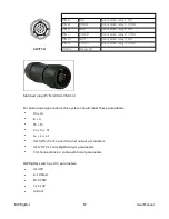
Page 59: ...nt also will give an alarm when out of limitation value When switch signal input BW RigRat will alarm when switch on This is for emergency alarm 4 20mA IN PIN A GND Switch input GND PIN B I O Switch input signal PIN D lin 4 20mA input positive PIN E lin 4 20mA input negative 4 20mA IN Others Reserved Matched plug P N 400 4105 010 BW RigRat 58 User Manual ...

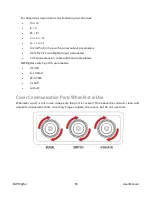
Page 60: ...ameters l Ct Lt are extension cable additional parameters BW RigRat switch port IS parameters l Ui 30V l Ii 100mA l Pi 0 75W l Ci 0nF l Li 0uH Cover Communication Ports When Not in Use Whenever a port is not in use make sure the port is covered This keeps the contacts clean and prevents inadvertent short circuiting Finger tighten the covers but do not use tools BW RigRat 59 User Manual ...

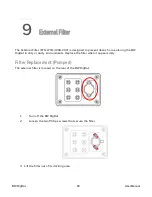
Page 61: ...W RigRat in dirty or dusty environments Replace the filter when it appears dirty Filter Replacement Pumped The external filter is located on the rear of the BW RigRat 1 Turn off the BW RigRat 2 Loosen the two Philips screws that secure the filter 3 Lift the filter out of its docking area BW RigRat 60 User Manual ...

Page 62: ...4 Dispose of the old filter properly 5 Press a new filter into place 6 Replace and tighten the two Philips screws Do not overtighten BW RigRat 61 User Manual ...

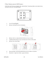
Page 63: ...Turn off the BW RigRat 2 Remove the Rain Protector if installed 3 Remove the four screws that hold the Sensor Cover in place 4 Carefully take out the O rings in each sensor location on the plate 5 Remove the current filters 6 Place new filters P N M01 2067 000 into each of the six locations 7 Place the O rings back in their original locations BW RigRat 62 User Manual ...

Page 64: ...8 Put the plate back in place 9 Tighten the four screws 10 Replace the Rain Protector if needed BW RigRat 63 User Manual ...

Page 65: ...etails about use restriction Note When the battery s charge falls below a preset voltage the instrument warns you by showing a critical error message and turn off automatically in 3 seconds You should charge the battery before turning it on again IMPORTANT If a major error that prevents the BW RigRat from functioning is found during startup the message Contact Service is shown on the display The i...

Page 66: ...overdue for a bump test or calibration either or both of these screens will be displayed to alert you Note If you do not click the button to acknowledge being informed of overdue tests the instrument will shut itself off in 300 seconds 5 minutes BW RigRat 65 User Manual ...

Page 67: ...tdown the instrument continues normal operation Note if you continue to hold the button during the second 3 second countdown it enters the main menu Note You cannot turn off the BW RigRat if it is in gas alarm Testing Alarm Indicators Under normal operation mode and non alarm conditions the backlight can be tested by turning the instrument on If you perform a bump test the buzzers and LEDs are tes...

Page 68: ...tion is required if l The sensor module has been replaced with one whose calibration is overdue l The defined period of time between calibrations has been exceeded according to the policy set for the instrument l If you have changed the calibration gas type without recalibrating the instrument l The sensor has failed a previous calibration BW RigRat 67 User Manual ...

Page 69: ...artup the screen displays Bump Overdue with a list of those sensors shown in red A bump test is required if the defined period of time between bump tests has been exceeded This interval is set by an administrator using Device Configurator BW RigRat 68 User Manual ...

Page 70: ...d on and then holding the button down through the 3 2 1 countdown followed by a second 3 2 1 countdown Entering Menu Mode 1 With the BW RigRat on hold the button down through the 3 2 1 countdown followed by a second 3 2 1 countdown 2 The password screen appears release the key 3 Enter the 4 digit password the default password is 0000 l Step from one position in the four character string to the oth...

Page 71: ...have been received by other devices on the network Exiting Menu Mode There are two ways to exit Menu Mode l If you do not press the button after 20 seconds it will revert to the main screen l Press the button until you reach Exit Diagnostic Mode In Diagnostic Mode the BW RigRat provides information about the instrument battery pump etc as well as a list of installed sensors and information about t...

Page 72: ...build time l RTC l Sensors Installed l Socket Raw Counts for all enabled sensors l Sensors Serial Number l Sensors Zero and Span raw counts l Sensors produced date and warranty l Battery capacity voltage current temperature SOH cycle counts l Battery current at idle mode Hold button to enter idle mode and calculate l RAEMet readings if installed l Noise sensor information if installed Hold to star...

Page 73: ...ow the screen displays OFF Release the button The instrument is now off Note Keep holding the button down at this screen for 10 seconds The BW RigRat will ask for the 4 digit password When the correct password is used the BW RigRat enters normal operation mode with diagnostic mode datalogging BW RigRat 72 User Manual ...

Page 74: ...re updates examine datalogs upload configuration data and more Download the free Device Configurator Mobile App Then follow the instructions for installation Android iOS Go to Device List to see which devices are paired Click Scan If your BW RigRat is in the Paired Devices list click on it When it connects it says Connected You can disconnect from a paired device by clicking its name A confirmatio...

Page 75: ...to your wireless network without permission l Personalize access regarding who can configure your wireless settings l Protect all data that is transmitted through the wireless network Check with your system administrator for the wireless security mode you should use Then set your Security Key Warning Using a network with security disabled is not recommended BW RigRat 74 User Manual ...

Page 76: ...egulator producing 0 5 liters per minute should be used and the calibration adapter must be installed on the diffusion model of the BW RigRat The instrument must be connected to a cylinder of calibration gas with supplied tubing Note If LEL and VOL sensors are installed always bump test the LEL sensor first 1 Turn on your BW RigRat by pressing and holding the button and allow the instrument to boo...

Page 77: ...the button once to confirm that you understand there are faults 6 After the audio visual test bump test the instrument is ready for the bump testing 7 Mount the calibration adapter and apply gas when the display shows Apply test gas now Otherwise the bump test will fail Also it may be necessary to change gas cylinders to provide the necessary gas for each sensor bump test 8 When the test is comple...

Page 78: ... If the Audio Visual test fails or some sensors fail their bump test the display will show results like this BW RigRat 77 User Manual ...

Page 79: ... the bump test will fail Important If one or more sensors fails a bump test be sure to calibrate those sensors The bump test is now complete If all the alarms and all sensors have passed and no sensor is due for a calibration the instrument is now ready for use BW RigRat 78 User Manual ...

Page 80: ...en shows another 3 second countdown for entering Menu Mode 3 Enter the password and accept the number 4 Press the button to advance to the next menu 5 Press and hold the button for 3 seconds to enter calibration 6 Press the button to start zero calibration Note If the BW RigRat has CO2 or Oxygen sensor after zero of fresh air it will continue to nitrogen for a zero calibration 7 Install the calibr...

Page 81: ...l and following the Honeywell guidelines provided in Honeywell training programs IMPORTANT Honeywell cannot guarantee the IP rating of an instrument that has been opened and not reassembled according to instructions Cleaning Use water and a soft cloth to clean the BW RigRat Do not use detergents or solvents Do not submerge the instrument underwater BW RigRat 80 User Manual ...

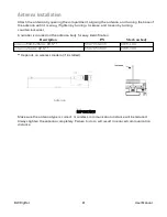
Page 82: ... the antenna body for easy identification Description P N Mark on body Antenna 868 928MHz RP N 550 7056 000 0188 1101 Antenna 2 4GHz RP N 550 7057 000 0188 3101 Depends on wireless modem if installed Antenna IMPORTANT Make sure the antenna type is correct or wireless communication distance will be reduced Always tighten the antenna completely Failure to do so will result in reduced communication d...

Page 83: ...ent 2 Remove the four screws that hold the sensor cover 3 Lift off the cover 4 Carefully lift out each sensor you wish to inspect or replace Sensor slots are keyed so that they can only accommodate specific types of sensors 1 Slot 1 IR IR low power or CO2 2 Slot 2 PID or IR or CO2 or EC 3 Slot 3 Catalytic combustion LEL or EC 4 Slot 4 IR or CO2 or EC 5 Slot 5 EC 6 Slot 6 EC BW RigRat 82 User Manua...

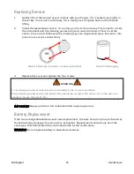
Page 84: ...n sensor module with socket Sensor indexing key 3 Replace the cover and tighten the four screws WARNING It is extremely important that sensors are installed in the correct orientation When installing a new sensor the plastic film should be on top of the sensor Once the sensor is installed remove the plastic film IMPORTANT Always perform a full calibration after replacing sensors Battery Replacemen...

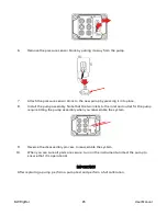
Page 85: ...n off the BW RigRat 2 Remove the four screws that hold the sensor compartment cover 3 Lift off the sensor compartment cover and turn it over 4 Remove the four screws that hold the pump assembly 5 Lift the pump assembly from the side farthest from the gas plate and slightly pull it away from the gas plate BW RigRat 84 User Manual ...

Page 86: ...inlets to the inlet and outlet for the pump require tilting the pump assembly when you reassemble the system 9 Reverse the disassembly process to reassemble the system 10 When you are sure all parts are secure turn on the instrument and test the pump to ensure that it is operational IMPORTANT After replacing a pump perform a pump test and perform a full calibration BW RigRat 85 User Manual ...

Page 87: ...P N W03 3045 000 it is typically removed for storage and must be attached before using it 1 If the BW RigRat is on turn it off Never attach or remove the RAEMet sensor without first turning off the instrument s power 2 Attach the RAEMet to the instrument s handle using the two U shaped bolts and the wingnuts Then attach the sensor to the bracket BW RigRat 86 User Manual ...

Page 88: ...he RAEMet sensor is firmly seated Do not turn the entire RAEMet sensor IMPORTANT If the RAEMet and BW RigRat s receptacle are not aligned properly electrical connections will not be made and the RAEMet sensor will not operate Also when the RAEMet sensor is not attached to the instrument make sure the cover is securely closed to keep moisture and debris from entering the base Note Do not remove the...

Page 89: ... programmed or selectively turned on or off The LED alarm indicators cannot be turned off Alarm Signals During each measurement period the gas concentration is compared with the programmed alarm limits for Low High TWA and STEL alarm If the concentration exceeds any of the preset limits the alarms are activated immediately to warn of the alarm condition In addition the BW RigRat alarms if the batt...

Page 90: ...nstrument fatal error Fail 2 beeps s 200ms s FAIL Blink red Sensor generic fail Negative 1 beeps s 200ms s OL Blink red PID Lamp 1 beeps s 200ms s LAMP Blink red PID lamp fail Remote Alarm 1 beeps s 200ms s Units in alarm in network detail screen Remote device alarm in closed loop network External Alarm 1 beeps s 200ms s External signal state in Input output state screen 4 20mA input digital input...

Page 91: ...onfidence beep Bump error icon at bottom of screen Cal Due Reverse IntelliFlash Confidence beep Cal error icon at bottom of screen Bump Due Reverse IntelliFlash Confidence beep Bump error icon at bottom of screen Datalog Full Reverse IntelliFlash Confidence beep Datalog memory is full Network Lost Reverse IntelliFlash Confidence beep Network error icon Compliance IntelliFlash Confidence beep When ...

Page 92: ...w LED Green LED Buzzer LCD Display Reading Startup Startup pattern Startup pattern Startup pattern Startup pattern Manual Alarms Test Under Normal Operation Mode and non alarm conditions the buzzer audible alarm and visible alarms can all be tested anytime by turning off the instrument or bump testing the instrument If any alarm does not respond check the alarm settings to make sure all alarms are...

Page 93: ...e Device Configurator App to set Buzzer and Light All On Contact authorized service center Lamp message when power on Lamp alarm Reasons Low ion concentration inside PID lamp especially in cold environment when first powered on Defective PID lamp or defective circuit Solutions Turn the unit off and back on Replace UV lamp Pump failed message Pump alarm Reasons Inlet probe blocked Direct connection...

Page 94: ...utions Try another AC charger or connect again The BW RigRat requires time to trickle charge the battery first before it can run normally and show messages on the LCD If you need replacement parts please contact an authorized Honeywell distributor BW RigRat 93 User Manual ...

Page 95: ... Set Span a Set Sensor Units a Set LEL Calibration Gas a Set LEL Measurement Gas a Get LEL PID CF value a Set PID Calibration Gas a Set PID Measurement Gas a Set Multi Calibration Gas a Set Gas Alarm Limits a Get Set bump test date and interval a Get Set calibration test date and interval a Get Set Alarm Mode a Set Inert Mode a Alarm Settings a Secure Beep a Set Intelli Flash a Set Intelli Flash i...

Page 96: ...dress a GPS On Off a Wi Fi On Off a Set Access Point SSID a Set Access Point Password a DHCP Enable a Set Server IP Address a Set Server Port a Set Network Security On Off a Set Network Security Keys a Security Mode Noise Sensor On Off a Get gas library information a Get Set custom gas list a Get Set password a Get Set secure level a Set power up welcome message a Get Set LCD idle timeout a Get Se...

Page 97: ...tor Set Switch Outputs a Set Digital Input On Off a Set Digital Input Alarm Point a Set 4 20mA Input On Off a Set 4 20mA Alarm Points a Policy Enforcement force on calibration bump a Average Type a DC security a BW RigRat 96 User Manual ...

Page 98: ...ff Power off in 300s Incompatible sensor and application firmware 4011 Contact your distributor Hold to power off Power off in 300s Bad battery Battery voltage too high or too low during charging 4013 Contact your distributor Hold to power off Power off in 300s No battery Power supplied from AC adapter 4015 Contact your distributor Hold to power off Power off in 300s Lost communication 4017 Contac...

Page 99: ...ration Click to acknowledge Power off in 300s Invalid wireless configuration 1011 Mesh Module Not Found Click to acknowledge Power off in 300s 1013 Wi Fi Module Not Found Click to acknowledge Power off in 300s 1017 Battery Charging Current Too Low Click to acknowledge Power off in 300s 1018 Battery NTC Fault Click to acknowledge Power off in 300s Temperature out of range battery cannot charge 1020...

Page 100: ...r Diffusion Calibration Device Configurator mobile application or manual Alarms Red Yellow Green bright LED alarm Buzzer alarm 108dBA 1m On screen indication of alarm conditions Datalogging Gas sensors and GPS data at one minute internal for 4 months Datalogging interval setting 1 to 3600 sec default 1 min Location Outdoor GPS 10m accuracy Optional RF Power Up to 4dBm 2 5mW BLE up to 17dBm 50mW Me...

Page 101: ... communication switching and 4 20mA Input Safe Area Charge Port AC CHG SAFE AREA Battery charger input DC5 7V 3A typical Connect to AC DC adapter Field charge from IS Barrier Solar Panel IS CHG HAZARDOUS Line Power Supply input to extend Instrument Runtime For Low Power version only RAEMet Port Serial Optional Port to RAEMet wind sensor Analog Switch Input Port 4 20MA IN Optional 4 20mA signal inp...

Page 102: ...00ppm 0 1ppm 4 to 131 F 20 to 50 C CARBON MONOXIDE CO 0 500ppm 1ppm 40 to 140 F 40 to 60 C CARBON MONOXIDE CO EXT RANGE 0 2000ppm 10ppm 4 to 131 F 20 to 50 C CARBON MONOXIDE CO H2 RESISTANT 0 2000ppm 5ppm 4 to 131 F 20 to 50 C HYDROGEN SUFLIDE H2S 0 100ppm 0 1ppm 40 to 140 F 40 to 60 C HYDROGEN SUFLIDE H2S EXT RANGE 0 1000ppm 1ppm 4 to 131 F 20 to 50 C SULFUR DIOXIDE SO2 0 20ppm 0 1ppm 4 to 131 F ...

Page 103: ...tice LEL Range Resolution Response Time Range 0 to 100 LEL Resolution 1 Response Time T90 30 sec Caution Refer to Technical Note TN 114 for LEL sensor cross sensitivities Refer to Technical Note TN 144 for LEL sensor poisoning BW RigRat 102 User Manual ...

Page 104: ...wing table Year First digit Year code Month Second digit Month code 2014 R January 1 2015 S February 2 2016 T March 3 2017 U April 4 2018 V May 5 2019 W June 6 2020 A July 7 2021 B August 8 2022 C September 9 2023 D October A 2024 E November B 2025 F December C Example RA indicates that the monitor is manufactured in the month of October in the year 2014 BW RigRat 103 User Manual ...

Page 105: ...pm 1 100 10 H2S Sensor Range ppm 1 100 N A H2S Low ppm 1 100 10 H2S High ppm 1 100 20 H2S STEL ppm 1 100 15 H2S TWA ppm 1 100 10 LEL Span LEL 10 60 50 LEL Sensor Range LEL 1 100 N A LEL Low LEL 10 60 10 LEL High LEL 10 60 20 O2 Span 1 30 18 O2 Sensor Range 1 30 N A O2 Low 1 30 19 5 O2 High 1 30 23 5 HCN Span ppm 1 50 10 HCN Sensor Range ppm 1 50 N A HCN Low ppm 1 50 4 7 HCN High ppm 1 50 25 BW Rig...

Page 106: ...om For RAE Toll free 1 888 749 8878 Email rae callcenter honeywell com RAE HEADQUARTERS RAE Systems by Honeywell 1349 Moffett Park Drive Sunnyvale CA 94089 USA Phone 408 952 8200 RAE tech honeywell com WORLDWIDE SALES OFFICES USA Canada 1 877 723 2878 Europe 800 333 222 44 41 44 943 4380 Middle East 971 4 450 5852 China 86 10 5885 8788 3000 Asia Pacific 852 2669 0828 BW RigRat 105 User Manual ...

Page 107: ...User Manual P N W03 4001 000 BW RigRat Revision E Honeywell September 2022 ...

Reviews: